Midmesh Panel
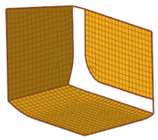
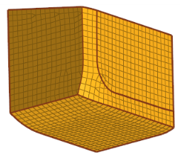
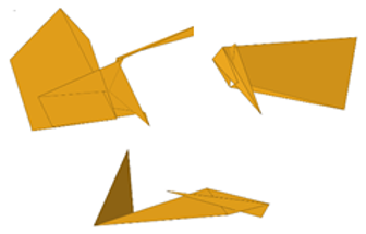
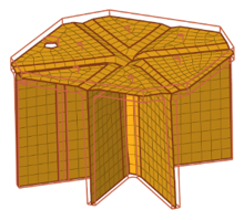
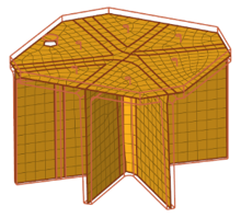
Use the Midmesh Panel to automatically generate a mesh at the midplane location, directly from the input geometry (components, elements, solids or surfaces), without first creating a midsurface.
Create Subpanel
Use the Create subpanel to control the resulting midmesh output.
| Option | Action | ||
|---|---|---|---|
| entity selector | Select the source used to create the midmesh. | ||
| destination comp | Choose where to organize newly elements. | ||
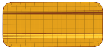
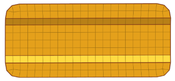
| ignore flat edges | Do not imprint flat edges from the input geometry to the midmesh.
|
||
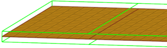
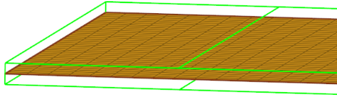
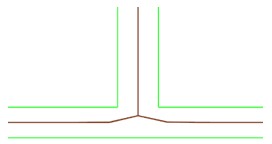
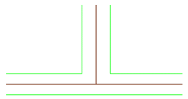
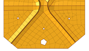
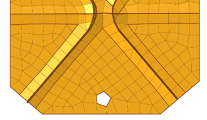
| flatten connections | Align/flatten the midmesh at ribs/connections.
|
||
| edit criteria | Opens the Criteria File Editor. | ||
| minimum size | Minimum element size allowed in the finalized mesh. This in
combination with the ‘suppress proximity edges factor’ and
'combine non-manifold edges factor’ can ensure that the output
mesh is ready for rebuild with the same criteria. Can only be modified in the Criteria File Editor. |
||
| suppress proximity edges factor | Remove 1D topology edges within the given factor of the
minimum size from the criteria file.
|
||
| combine non-manifold edges factor | Join non-manifold edges within the given factor of the
minimum size from the criteria file.
|
||
| defeature openings with width < | Remove small holes and openings less than the specified width.
|
Edit Edge Subpanel
Use the Edit Edge subpanel to repair 1D topology edges.
| Option | Action | ||
|---|---|---|---|
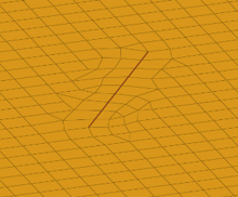
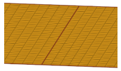
| create mid-edge | Create a new mid-edge, using the input geometry as a guide.
|
||
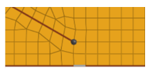
| split by two n odes | Create a new edge between two nodes.
|
||
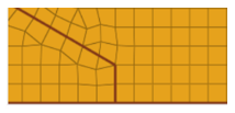
| split by node-edge | Create a new edge between a node and an edge, using a
shortest, tangential or mixed path.
|
||
| delete edge | Delete an edge.
|
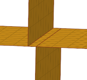
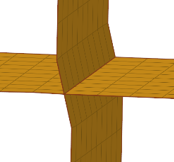
||
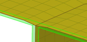
| t-edge align | Align/flatten a t-connection edge to a surface.
|
||
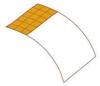
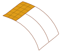
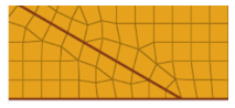
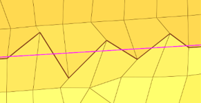
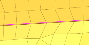
| by geom edge | Align mesh edges to input geometry lines and smooth the mesh,
or imprint new geometry edges onto the midmesh.
|
||
| replace node | Opens the Replace Panel. | ||
| edit element | Opens the Edit Element Panel. | ||
| edges | Opens the Edges Panel. | ||
| delete | Opens the Delete Panel. | ||
| align nodes | Opens the Node Edit panel, align node subpanel. | ||
| project | Opens the Project Panel. |

Edit Face Subpanel
Use the Edit Face subpanel to correct issues with midmesh faces.
| Option | Action | ||
|---|---|---|---|
| fill face | Create a mesh within a closed 1D topology loop, attempting to
keep tangency. Optionally, the 1D loop can be deleted, keeping
only free and non-manifold edges.
|
||
| repair face | Attempt to fix topological problems (holes/gaps/cracks,
intersections, slivers, overlaps) in the mesh and remesh the face.
|
||
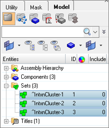
| detect intersections | Detect intersecting element clusters and holes/gaps/cracks,
and create element sets for further handling.
|
||
| align face | Align a selection of elements to an input geometry face, with
optional offset and locking of boundary nodes.
|
||
| replace node | Opens the Replace Panel. | ||
| edit element | Opens the Edit Element Panel. | ||
| delete | Opens the Delete Panel. | ||
| project | Opens the Project Panel. |