Extract Midsurfaces
Use the Automatic tool to extract the midsurface of sheet metal stampings, molded plastic parts with ribs, and other parts that have thickness clearly smaller than width and length.
-
From the Geometry ribbon, Create tools, click

Figure 1. - Optional:
On the guide bar, click
 to define midsurface options.
Tip: On the guide bar, click  to open the
Advanced Selection dialog, from which you can
filter geometry further by selecting a subset of entities based on
additional selection methods, such as By Component or By
Assembly.
to open the
Advanced Selection dialog, from which you can
filter geometry further by selecting a subset of entities based on
additional selection methods, such as By Component or By
Assembly.
Automatic Options
- Destination component
- Select which component newly created midsurfaces are placed in.
- Mask input geometry
- Hide input midsurfaced geometry in the modeling window upon exiting the context.
- Extract across components
- Extract the midsurface of one component at a time.
- Clear existing plates
- Clear existing plates prior to midsurface extraction.
- Midsurface method
- Select a method for midsurfacing.
-
- Planes + Sweeps + Offsets
- Identify the places where a piece of plane or a piece of a sweep surface can be
used as a middle surface. A middle surface is constructed at the remaining places
in the model, for example the places where planar or sweep surface pieces cannot
be used as a middle surface, by the same algorithm as in offset via the offset of
the model's sides.
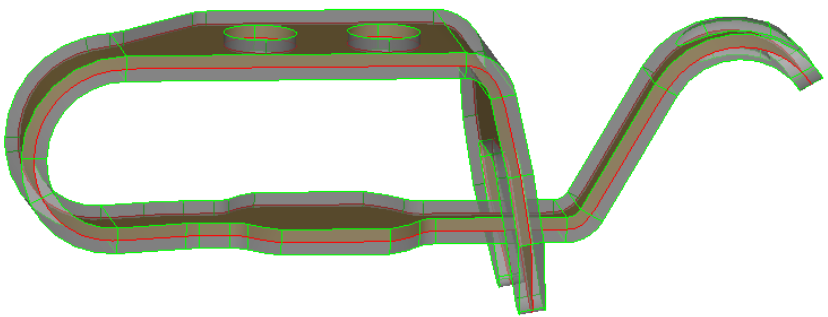
Figure 2. - Planes + Offsets
- Identify the places in the model where a piece of plane can be used as a middle
surface. At the remaining places in the model, for example the places where planar
pieces cannot be used as a middle surface, the same algorithm as in Offsets is
used to construct the middle surface via the offset of the model's sides.
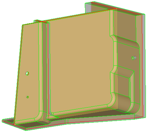
Figure 3. - Offsets
- Create pieces of the middle surface by offsetting the model's side surfaces
towards the middle. This is the traditional approach for midsurfacing in HyperWorks X.
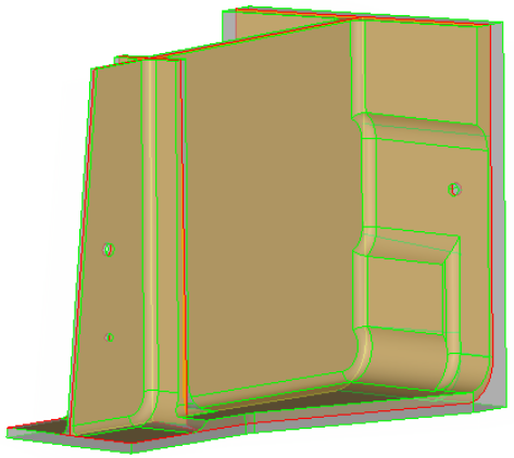
Figure 4. - Skin Offset
- Generate a midsurface by duplicating and offsetting the inner skin surfaces (those with the smallest area), and assign them a constant thickness.
- Offset midsurface position
- Select a method for positioning midsurfaces when the thickness of thin solids is inconsistent.
- Align steps
- Select a method for offsetting the midsurface.
- User-specified
- Change the offset of the midsurface, using a value from 0 to 1, in order to specify the offset from the largest side of the volume.
- Use base surfaces
- Use base surfaces info for midsurface extraction.
- Cleanup tolerance
- Select a method for defining the cleanup tolerance.
- Maximum R/T ratio
- If the maximum R/T ratio (radius/thickness) is greater than this value, then that section of the solid will not be midsurfaced.
- Define thickness limits by
- Select a method for defining thickness limits.
- Max/Min thickness
- Change the min/max thickness ratio for midsurface extraction. This is the highest acceptable ratio of the thickest plate’s thickness to that of the thinnest plate. Thicknesses above this ratio are ignored.
- Minimum thickness
- Change the minimum thickness of the plates in the part that should be midsurfaced. Plates with a thickness smaller than this value will not be midsurfaced.
- Maximum thickness
- Change the maximum thickness of the plates in the part that should be midsurfaced. Plates with a thickness greater than this value will not be midsurfaced.
Keyboard Shortcuts & Mouse Controls
| To do this | Press |
|---|---|
| Exit tool | Esc |