Solids are closed volume of surfaces that can take any shape. Solids are
three-dimensional entities that can be used in automatic tetra and solid meshing.
The surfaces defining a solid can belong to multiple component collectors. The display of a
solid and its bounding surfaces are controlled only by the component collector to which the
solid belongs.
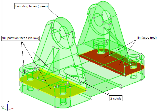
Bounding Surface
A bounding surface defines the outer boundary of a single solid.
Bounding surfaces are shaded green by default.
A bounding surface is unique and is not shared with any other solid. A single solid
volume is defined entirely by bounding surfaces.
Fin Surface
A fin surface has the same solid on all sides, that is, it acts as a fin inside of a
single solid.
Fin surfaces are shaded red by default.
A fin surface can be created when manually merging solids or when creating solids
with internal fin surfaces.
Full Partition Surface
A full partition surface defines a shared boundary between one or more solids.
Full partition surfaces are shaded yellow by default.
A full partition surface can be created when splitting a solid or when using Boolean
operations to join multiple solids at shared or intersecting locations.
Figure 1.
Create Bounding Solids
Use the Bounding tool to create solids from enclosed surface
volumes.
From the Geometry ribbon, Create tools, click Solids > Bounding.
Figure 2.
Optional: On the guide bar, click to define additional
options.
Select bounding surfaces.
On the guide bar, click Find to detect bounding surface
sets.
Left-click on bounding surfaces in the modeling window.
Create bounding solids.
Click Create All to
create bounding solids from all found/selected surface bounds.
Create individual bounding solids by left-clicking on a selected
bounding surface.
Figure 3.
Tip:
Review each found/selected bounding surface group by clicking and on the guide bar.
Click on the guide bar to reset all found bounding surfaces.
Click Find to select
bounding surfaces interactively in the modeling window after reset.
Create Spheres
Use the Sphere tool to create spheres with solid or bounding
surfaces.
From the Geometry ribbon, Create tools, click Solids > Sphere.
Figure 4.
Create sphere.
Left-click on geometry or in space to create the sphere's center
point.
Move your mouse to uniformly resize and draw the sphere.
Left-click to create the sphere.
Modify the size and location of the sphere.
Resize the sphere by editing the radius in the microdialog and pressing Enter.
Click on the face of the sphere and drag the slider to adjust the
size.
Click in the microdialog to translate and rotate the sphere using the
Move tool.
Figure 5.
Tip:
Click in the microdialog to fit the sphere around a selected
object.
Click in the microdialog to fill the shape.
While placing or editing the sphere, use snap points
to snap to predefined points on your model, such as surface boundary fixed
points or mid points of surfaces.
Create Boxes
Use the Box tool to create boxes with solid or bounding
surfaces.
From the Geometry ribbon, Create tools, click Solids > Box.
Figure 6.
Create box.
A preview of the box displays at your cursor's position in the modeling window.
Left-click on geometry or in space to create the corner point for the
box's base.
Move your mouse to resize and draw the box's base.
Left-click to create the box's base.
Move your mouse to set the height of the box.
Left-click to create the box.
Modify the size and location of the box.
Resize the box by editing the length, width, and height in the microdialogs and pressing Enter.
Click on a face of the box and drag the slider to adjust its
dimension.
Click in the microdialog to translate and rotate the box using the
Move tool.
Figure 7.
Tip:
Click in the microdialog to fit the box around a selected object.
Click in the microdialog to fill the shape.
While placing or editing the box, use snap points to
snap to predefined points on your model, such as surface boundary fixed
points or mid points of surfaces.
Create Cylinders
Use the Cylinder tool to create cylinders with solid or
bounding surfaces.
From the Geometry ribbon, Create tools, click Solids > Cylinder.
Figure 8.
Create cylinder.
A preview of the cylinder displays at your cursor's position in the modeling window.
Left-click on geometry or in space to create the center point for the
cylinder's base.
Move your mouse to uniformly resize and draw the radius for the
cylinder's base.
Left-click to create the cylinder's base.
Move your mouse to set the height of the cylinder.
Left-click to create the cylinder.
Modify the size and location of the cylinder.
Resize the cylinder by editing the radius and height in the microdialogs and pressing Enter.
Click on a face of the cylinder and drag the slider to adjust the
size.
Click in the microdialog to translate and rotate the cylinder using
the Move tool.
Figure 9.
Tip:
Click in the microdialog to fit the cylinder around a selected
object.
Click in the microdialog to fill the shape.
While placing or editing the sphere, use snap points
to snap to predefined points on your model, such as surface boundary fixed
points or mid points of surfaces.
Bounding Options
Create in
Select which component newly created solids are placed in.

 to define additional
options.
to define additional
options.
 and
and  on the guide bar.
 on the guide bar to reset all found bounding surfaces.
 in the microdialog to translate and rotate the sphere using the
Move tool.
in the microdialog to translate and rotate the sphere using the
Move tool.
 in the microdialog to fit the sphere around a selected
object.
in the microdialog to fit the sphere around a selected
object.in the microdialog to fill the shape.

 in the microdialog to fill the shape.