Nodes
Nodes are the most basic finite element entity. A node represents a physical position on the structure being modeled.
A nodes is used by an element entity to define the location and shape of that element. It is also used as temporary input to create geometry entities.
A node may contain a pointer to other geometric entities and can be associated directly to them.
Nodes are considered to be used if they are referenced in the definition of an element, system, vector, group, load, equation, or are referenced by any card image on any HyperWorks X entity. Unused nodes and any loads that are attached to unused nodes are automatically deleted .
Nodes can not be organized into components. Nodes can also be organized into HyperWorks X include files, which defines the solver include file they will be exported to.
A node as displayed a small circle or sphere, depending on the mesh graphics mode. Its color is always yellow.
Create Nodes
Use the Points tool to create nodes on geometry surfaces and lines or in space. Nodes can be used to establish reference locations for geometry construction and meaningful snap locations for use with other tools.
-
From the Geometry ribbon, Create tools, click the Points tool.

Figure 1. -
Create nodes.
- Left-click on geometry or in space.
- Left-click in the modeling window and enter X, Y, and Z coordinates in the microdialog, then press Enter.
- Interpolate nodes by holding Ctrl while left-clicking new or existing nodes. Interpolate the midpoint of two nodes or the center of three nodes, or enter a number of nodes to interpolate in the microdialog and press Enter.
Figure 2.
Edit Nodes
Use the Points tool to edit nodes on geometry or in space.
-
From the Geometry ribbon, Create tools, click the Points tool.
Figure 3. -
In the microdialog, edit the X, Y, and Z coordinates
and press Enter.
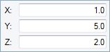
Figure 4.
Interpolate Nodes
Use the Extract Points tool to interpolate nodes to divide a line or edge into equal parts as references for use with other tools.
-
From the Geometry ribbon, Create tools, click the Extract Points tool.

Figure 5. -
In the microdialog, enter the number of nodes to
extract and press Enter.
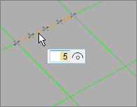
Figure 6.
- Re-interpolate the number of nodes on the selected line by entering a new value in the microdialog and pressing Enter.
- When interpolating nodes from multiple lines, the same number of nodes will be created on each line and distributed evenly along their respective source line’s length.
- When interpolating nodes from a closed loop, the start and end points are the same, but separate nodes will be created at each location. To divide a circle into four equal lines, interpolate five nodes.
Find Curve Center
Use the Extract Points tool to find the center of an arc or fillet, or find the center of multiple curve segments.
-
From the Geometry ribbon, Create tools, click the Extract Points tool.
Figure 7. -
In the microdialog, click
 .
Note: When calculating the curve center of multiple lines, a single node is created at the best matching curve center of the combined lines.
.
Note: When calculating the curve center of multiple lines, a single node is created at the best matching curve center of the combined lines.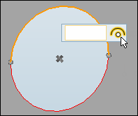
Figure 8.
Keyboard Shortcuts & Mouse Controls
| To do this | Press |
|---|---|
| Create point/node | Left Mouse Click |
| Edit point/node | Double Click |
| Interpolate points/nodes or create midpoint | Ctrl + Left Mouse Click or Left Mouse Drag |
| Lock direction while dragging | Shift + Left Mouse Click |
| Exit tool | Esc |
Supported Solver Cards
Solver cards supported for nodes.
Abaqus
| Card | Description |
|---|---|
| *NFILL | Generates nodes for a region of a mesh by filling in nodes
between two bounds. Note: Resolved to individual entities on
import, and are written back on export the same
way.
|
| *NGEN | Generates nodes incrementally. Note: Nodes can only be created
incrementally between two nodes.
Nodes generated along a parabola or curve are not supported (LINE=P or C parameter is not supported). SYSTEM parameter is currently unsupported. Resolved to individual entities on import, and are written back on export the same way. |
| *NODE | Defines nodal coordinates. Note: The
SYSTEM parameter is created
automatically during export based upon the type of reference
coordinate system that is assigned to the nodes.
The card image for a node is displayed in global Cartesian coordinates in HyperWorks X. |
ANSYS
| Card | Description |
|---|---|
| N | Defines a node. |
| N | Defines a node. |
| N | Defines a node. |
| NBLOCK | Defines a node. |
EXODUS
| Card | Description |
|---|---|
| NODE |
LS-DYNA
| Card | Description |
|---|---|
| *NODE | Defines a node and its coordinates in the global coordinate
system. Note: Card can be previewed, but not
edited.
|
| *NODE_RIGID_SURFACE | Defines a rigid node and its coordinates in the global
coordinate system. Note: Card can be previewed, but not
edited.
|
Nastran
| Card | Description |
|---|---|
| GRID | Defines the location of a geometric grid point, the
directions of its displacement, and its permanent single-point
constraints. Note: Permanent single point constraint field
supported for feinput only. On export, equivalent SPC cards
are output.
|
| SPOINT | Defines scalar points. Note: Supported the same way
GRID is supported. On import or
export, all nodes that are designated to be SPOINT will be
converted to nodes at the origin.
|
OptiStruct
| Card | Description |
|---|---|
| GRID | Defines the location of a geometric grid point of the
structural model, the directions of its displacement, and its permanent single-point
constraints. Note: Bulk Data Entry
Exported in large field format by the optistructlf template. |
| SPOINT | Defines sets of single-point constraints, enforced
displacements for static analysis, and thermal boundary conditions for heat transfer
analysis. Note: Bulk Data Entry
Ideally a scalar point has no location, but in HyperWorks X it is represented as a node. |
PAM-CRASH
| Card | Description |
|---|---|
| CNODE/ | Defines a common node. |
| NODE/ | Defines a node. |
Permas
| Card | Description |
|---|---|
| $COOR | Defines nodal points and their coordinates. |
Radioss
| Card | Description |
|---|---|
| /CNODE | Defines the coordinate of common node, which could be
merged to the nearest selected NODE or CNODE. Note: Block Format Keyword
|
| /NODE | Defines the coordinate of node, which is fundamental unit
of graphic in structure. Note: Block Format Keyword
|
Samcef
| Card | Description |
|---|---|
| .NOE | Defines the coordinates of the nodes of the structure. |