Points
A point is a zero-dimensional geometric entity.
A free point is a zero-dimensional geometry entity in space that is not associated with a surface. It is displayed as a small "x", and its color is determined by the component collector to which it belongs. These types of points are typically used for weld locations and connectors.
A fixed point is a zero-dimensional geometry entity that is associated with a surface. It is displayed as a small "o", and its color is determined by the surface to which it is associated. The automesher places a node at each fixed point on the surface being meshed. A fixed point that is placed at the junction of three or more non-suppressed edges is called a vertex or vertex point. Such vertices cannot be suppressed (removed).
Create Points
Use the Points tool to create points on geometry surfaces and lines or in space. Points can be used to establish reference locations for geometry construction and meaningful snap locations for use with other tools.
-
From the Geometry ribbon, Create tools, click the Points tool.

Figure 1. -
Create points.
- Left-click on geometry or in space.
- Left-click in the modeling window and enter X, Y, and Z coordinates in the microdialog, then press Enter.
- Interpolate points by holding Ctrl while left-clicking new or existing points. Interpolate the midpoint of two points or the center of three points, or enter a number of points to interpolate in the microdialog and press Enter.
 Figure 2.
- Create points at predefined points on geometry, such as end, middle, center, and intersection points. When interpolating points, you can also snap to points along the x, y, and z axis.
- Copying and pasting topology vertices (fixed points) generates free points and organizes them in the same component.
Edit Points
Use the Points tool to edit points on geometry or in space.
-
From the Geometry ribbon, Create tools, click the Points tool.
Figure 3. -
In the microdialog, edit the X, Y, and Z coordinates
and press Enter.

Figure 4.
Interpolate Points
Use the Extract Points tool to interpolate points to divide a line or edge into equal parts as references for use with other tools.
-
From the Geometry ribbon, Create tools, click the Extract Points tool.

Figure 5. -
In the microdialog, enter the number of points to
extract and press Enter.
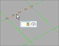
Figure 6.
- Re-interpolate the number of points on the selected line by entering a new value in the microdialog and pressing Enter.
- When interpolating points from multiple lines, the same number of points will be created on each line and distributed evenly along their respective source line’s length.
- When interpolating points from a closed loop, the start and end points are the same, but separate points will be created at each location. To divide a circle into four equal lines, interpolate five points.
Find Curve Center
Use the Extract Points tool to find the center of an arc or fillet, or find the center of multiple curve segments.
-
From the Geometry ribbon, Create tools, click the Extract Points tool.
Figure 7. -
In the microdialog, click
 .
Note: When calculating the curve center of multiple lines, a single point is created at the best matching curve center of the combined lines.
.
Note: When calculating the curve center of multiple lines, a single point is created at the best matching curve center of the combined lines.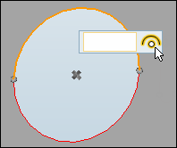
Figure 8.
Keyboard Shortcuts & Mouse Controls
| To do this | Press |
|---|---|
| Create point/node | Left Mouse Click |
| Edit point/node | Double Click |
| Interpolate points/nodes or create midpoint | Ctrl + Left Mouse Click or Left Mouse Drag |
| Lock direction while dragging | Shift + Left Mouse Click |
| Exit tool | Esc |