Surfaces
A surface represents the geometry associated with a physical part. A surface is a two-dimensional geometric entity that may be used in automatic mesh generation.
The color of a surface is determined by the component collector to which it belongs.
A surface is comprised of one or more faces. Each face contains a mathematical surface and edges to trim the surface, if required. When a surface has several faces, all of the faces are maintained as a single surface entity. Operations performed on the surface affect all the faces that comprise the surface. In general, HyperMesh automatically uses the appropriate number of and type of surface faces to represent the geometry.
The perimeter of a surface is defined by edges. There are four types of surface edges.
Surface edges are different from lines and are sometimes handled differently for certain operations.
- Free Edges
- A free edge is an edge that is owned by only one surface.
- Shared Edges
- A shared edge is an edge that is owned, or shared, by two adjacent surfaces.
- Suppressed Edges
- A suppressed edge is shared by two surfaces but it is ignored by the automesher.
- Non-Manifold Edges
- A non-manifold edge is owned by three or more surfaces.
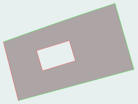
Patch Surfaces
Use the Patch tool to create patch surfaces between free lines that are not connected or surface edges.
-
From the Geometry ribbon, Create tools, click .

Figure 1. -
Patch missing surfaces in the following ways:
- If you use the Find option, simply click a highlighted surface to patch it.
- Click Patch All on the guide bar.
- While left-clicking, drag an edge to another edge.
- Select multiple edges around the missing surface, then click an edge that has already been selected.
- Double-click an edge loop.
- Click the arrow buttons on the guide bar to cycle through found surfaces.
- Copying and pasting solid faces generates surfaces and organizes them in the same component.
- HyperWorks X attempts to select the appropriate tangency setting for the surface created, but you can change the tangency by clicking on the surface while it is still selected.
- Delete surfaces by left-clicking on a selected surface.
- Hovering over a target line displays a preview surface.
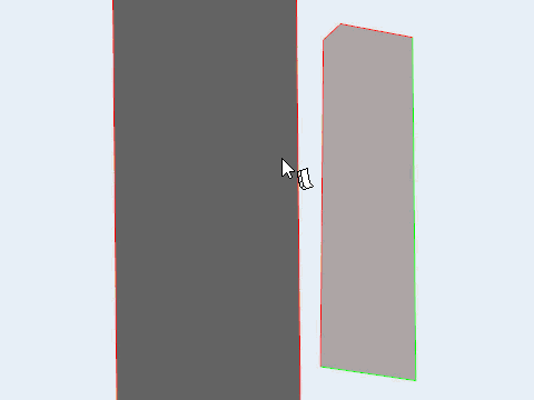
Extend Surfaces
Use the Extend tool to create tangent or normal extension surfaces.
-
From the Geometry ribbon, Create tools, click .

Figure 2. -
Extend the surface by entering a length in the microdialog and pressing Enter, or
pulling the arrow.
- Maintain edge angles by clicking
 .
. - Auto-trim intersecting surfaces by clicking
 .
. - Constrain line drag to one direction, then use snap points to extend surfaces by distances relative to existing geometry, even if the reference points are not on the same plane as the surface being extended.
Cross Extend Surfaces
Use the Cross Extend tool to extend surfaces to meet each other, or other target surfaces.
-
From the Geometry ribbon, Create tools, click .

Figure 3. - Optional:
On the guide bar, click
 to define cross extension
options.
to define cross extension
options.
-
Extend surfaces.
- Click Extend on the guide bar.
- Left-click a selected surface.
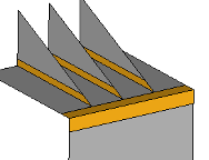
Figure 4.
Offset Surfaces
Use the Offset tool to offset surfaces or solids in a normal direction.
The topology of the surface edges (free, shared edges, and so on) is maintained during the offset function. Some individual surfaces will be trimmed or extended to maintain the connectivity.
-
From
the Geometry ribbon, Create
tools, click .

Figure 5. - Optional:
On the guide bar, click
to define offset options.
-
Offset
surfaces.
- Click-and-drag selected surfaces.
- In the microdialog, enter an offset value.
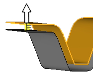
Figure 6.
- Offset surfaces in the opposite direction of the surface normal by entering a negative offset value.
- On the guide bar, click
 to open the
Advanced Selection dialog, from which you can
filter geometry further by selecting a subset of entities based on
additional selection methods, such as By Component or By
Assembly.
to open the
Advanced Selection dialog, from which you can
filter geometry further by selecting a subset of entities based on
additional selection methods, such as By Component or By
Assembly.
Surfaces Options
Cross Extend
- Define using
- Select whether to extend surfaces by a thickness multiplier or by a maximum distance.
- Distance
- Change the maximum distance to extend surfaces.
- Minimum angle
- Change the minimum angle to extend surfaces.
- Maximum angle
- Change the maximum angle to extend surfaces.
- Maintain edge angles
- Do not change the angle of surface edges during extension.
- Allow shortening
- Shorten edges, within the extension tolerance, so that edges meet.
- Extend as new surface
- Create extended edges as new surfaces rather than a continuation of the existing surfaces.
- Choose targets
- Enable target surface selection.
Offset
- Continuous offset
- Preserve connection with adjacent surfaces after offset.
Keyboard Shortcuts & Mouse Controls
| To do this | Press |
|---|---|
| Append to selection | Ctrl + Left Mouse Click |
| Remove selection | Shift + Left Mouse Click |
| Cycle adjacent surfaces to extend Extend tool |
Tab |
| Switch between selecting Source and Target surfaces Cross Extend tool |
Tab |
| Disable snapping | Alt + Left Mouse Drag |
| Switch active tool | Ctrl + Tab |
| Exit tool | Esc |