Update Links
Update the attributes associated with a link, such as reconnection rule, link references, and link state.
- Part replacement
- Modify link rules
- Modify link states
If a part replacement needs to be performed, the browser provides quick tools to update one or more connectors with the link referencing the new redesigned part. The following sections present steps to edit and update the link rule and the link state attributes as well as the part replacement.
You can update links in the following ways:
-
Directly edit column data in the Connector Browser.
- In the Connector Browser, select the link(s) or connector(s) to update.
- Click a field to edit the current value or select a new value.
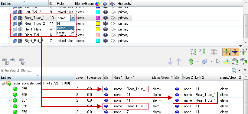
In the Link Entity Browser, updates can be performed on a single or multiple selected links. When you update a link in the Link Entity Browser, link references will be automatically updated in the Connector Entity Browser. In the Connector Entity Browser, updates can be performed for an individual link on a single or multiple selected connectors in the Connector Entity Browser.For example, quickly change the reconnection rule from the Rule column, or change the link state from the Elems/Geom column. Update links for the purpose of part replacement by entering a new link ID or link name in the Link Entity Browser. Part replacement can also be performed on single or multiple selected connectors in the Connector Entity Browser by entering a new link ID or link name in the Link column.
Figure 1. -
Using the Update Link option in the Connector Browser's right-click context menu.
-
Select the connectors from the browser for which one or more links need
to be updated.
The connectors can also be selected from the graphics area by using the Selector button in the action modes tool set. The connectors selected in the graphics area will be highlighted in the browser tree.
-
Right-click one of the highlighted connectors and select
Update Link from the context menu.
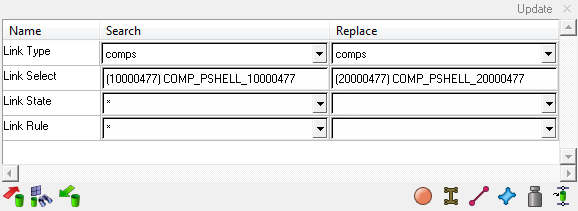
An Update Link dialog opens at the bottom of the Connector Browser. All highlighted connectors will be affected by the subsequent update link action.Note: If the Update Link dialog is still open from a previous update link operation, all blue highlighted connectors will be affected when the update link function is performed again.
The lines for Link State and Link Rule are grayed out by default in the Update Link dialog. When the extended information in the Connector Entity Browser configuration window is activated, these lines become active as well.
-
Fill in the fields in the Search column.
Due to this selection, the links of the selected (highlighted) connectors are filtered down to the links which fit to all given search attributes. Only the remaining links are taken into account for the subsequent attribute replacement.Note: Not all of the search attributes have to be defined; an asterisk can be used.
-
Fill in the fields in the Replace column.
All the remaining links will be updated with the attributes defined by these attributes.Note: Not all of the replace attributes have to be defined; an asterisk can be used. The prior attributes are maintained.
-
Click Update to acknowledge and execute the
operation.
Note: Not every combination of search and replace attributes are valid. For example, it is not possible to select the asterisk for the Link Select field in the Search column and replace it with a concrete link. This helps to prevent global creation of unwanted modifications.

Figure 2.
-
Select the connectors from the browser for which one or more links need
to be updated.