Append the entity attributes associated with components, properties, and
materials to the browser as column data to facilitate fast and efficient
review, editing, sorting, and filtering. Columns can be reorganized by
dragging them to the desired position.
Entity attributes can be filtered in their respective columns when in
the Include, Component, Material, Property, and Assembly views.
Assembly view in Model Browser
Quickly view an isolated list of all the assemblies in your model using
the new Assembly view in the Model Browser.
Metadata in Entity Editor
A new section has been added to the Entity Editor to allow for easy
review and editing of metadata. This is available for all entity types,
and is also supported for appending as column data in relevant browser
views.
Enhancements
Duplicate extended entity selection for components
Maintain associativity between elements and geometry using the
"Duplicate" selection method added to the extended entity selection menu
in the Reflect, Translate, and Rotate panels.
2D plotel elements supported by Mask Browser
The Mask Browser now supports Plotel3 and Plotel4 elements.
Maintain entity name when duplicating entities
The original name assigned to an entity is retained when creating new
entities using the "Duplicate" option in the Model Browser.
Select IDs in browser spinbox
Select entity IDs from the spin box located in the top corner of the
browser.
Entity management in Include files
Newly created entities are automatically organized into the Include file
of their current collector.
This functionality is supported for nodes, elements, lines, points,
surfaces, solids, contact surfaces, loads, equations, systems, vectors,
and beam sections.
Entity creation respects the Include file in which it was created.
ID Manager enhancements
Entities are listed by ID pools per Include file or the Master Model.
Duplicate IDs are permitted when renumbering a model for certain
entities when "Allow Duplicate IDs on Correction" is selected. CSV
export captures min and max IDs and per include entity counts, while
import prompts you if your model contains overlapping ID ranges.
Undefined entities support for components
Undefined entities now support components.
Note: Components are not
created for undefined connectors.
Resolved Issues
The From overflow column in the ID Overflow List dialog
shows incorrect IDs for overflow entities.
Closing the ID Manager dialog while a push panel was
active results in a crash.
When an entity name is the same as another entity’s ID, you cannot change
its ID and color. This is valid for all entity types listed in the Model Browser.
Adjusting orientation using the Orientation Review tool deletes
elements.
Updating pressure direction changes the magnitude of pressure.
Saving and reopening HyperMesh models that
contain weld data causes segmentation errors.
Face selection issues.
Displaying load magnitudes, inconsistently shows both fixed and scientific
formats.
Moving the application from one monitor to another occasionally fails to
show the panel area correctly.
The "Export All Self Contained" selection option, accessed from the Include
view context menu does not use the updated command.
Elements are organized incorrectly when you set Destination Component to
"Original Collector" in the Transformation dialog.
Using the Shift+Tab keyboard
shortcut in a panel moves the selection outside of the panel on Linux.
The Reflect panel assigns nodal thickness to incorrect nodes.
Character limitation while typing in an input field of a panel.
Graphics
New Features
2160p Ultra High Definition support
2160p Ultra High definition is supported in HyperWorks products with proper DPI scaling and
sharper graphics area.
Freetype fonts supported in graphics area and HyperMesh panels
Freetype fonts have been added and bundled for smoother anti-aliased
fonts being rendered in the graphics areas within HyperWorks products and HyperMesh panels.
Enhancements
Element Quality view
Review your model's overall element quality categorized as Worst, Fail,
Warn, Good and Ideal using the Quality Index Range (QI Range) legend
that has been added to the Element Quality view.
Improved graphics selection and performance improvements for displaying
nodes in graphics
The rendering of nodes that are being displayed has been accelerated
with enhanced graphics rendering techniques.
Selection picking has also been improved.
Known Issues
The following known issues will be addressed in a future release as we continuously
improve performance of the software:
In certain cases, rotational framerates will be reduced while entity types
such as springs/gaps, element handles,loads, and so on are visible.
Tip: Enabling the optimize view ctrls
checkbox (Preferences > Graphics) may increase rotation framerates.
If you are experiencing performance issues for animations, interactive
meshing, and product stability, it is recommended that you use Windows
NVIDIA drivers version 419.53 (or higher) for HyperWorks 2019 which
introduces enhancements in these areas.
Resolved Issues
Edge selection does not work while spherical clipping is on.
Connectors
New Features
Undo-Redo connector support
Undo/redo operations are supported by all connector related
functionality.
Connector Groups
Connectors are now organized inside of the newly supported connector
group entity, and not components.
Connectors will be automatically reorganized into connector groups when
you import/export a legacy HyperMesh model
or solver deck that has connectors organized in components. The
connector group that gets created during the reorganization will be
assigned the same name and ID as the component that originally held the
connectors.
Newly created connectors will be organized in the root level, known as
Master Connector Group.
Create, delete and rename connector groups from the Connector Browser's Link view. Connectors can be moved
to/from connector groups.
Connector support for configuration management
Unrealized connectors can be made active/inactive based on their link
state. If a connector's link is inactive, then the connector will
automatically be made inactive. This functionality is supported for
connectors with part links, component links, or property links.
Second pass projection for RADIOSS welds
Find exact contact points with the "Use 2nd projection" parameter. This
parameter is supported for all realizations, where nodes are on a tria
or quad face, as well as for all 1D element realizations, hexa element
realizations (only if shell gap is used), and penta realizations (only
if consider shell thickness and offset for solid positioning is
off).
Remove links from connectors
Remove links from connectors in the Connector Browser, Component Link view with the "Remove From Connectors" right-click
contextual menu option. You can choose to remove links from selected,
displayed, or all connectors. Layers can be automatically updated once
links have been removed with the "Update Layer" option in the
Remove From Connectors Settings dialog.
Enhanced display functionality for HAZ element
Automatically update the display of HAZ elements associated with
connectors and link entities that are being isolated, displayed, or
hidden with the "Consider HAZ Elements" option in the Browser
Configuration dialog.
Reduce search/isolation to specific components and elements
Specify a type of link and weld elements to isolate when you are
reviewing a realization with the "Filter Links to" option in the
Browser Configuration dialog. You can choose to
isolate an entire link component, only the elements on which the
projection falls, or the elements on which the projection falls along
with the elements which connects connector FE.
Get link information for resolved entities
Get link information for resolved entities and organize this information
per link index using the
hm_ce_getresolvedlinkentities API. The output
will show ‘entity-id’ if a link entity is present in the current model,
otherwise it will show ‘0’.
Unregister realized entities
Unregister realized entities from connectors using the
*CE_FE_UnregisterRealizedEntities API. Once you
have successfully unregistered realized entities from a connector, the
state of the connector is changed to Modified (blue). The realized
entities that were unregistered from the connectors will not be deleted
during connector “unrealization” and “deletion with FE”.
Enhancements
Connector support for *entitysupressactive API
The *entitysupressactive API now supports connector
entities, and can be used to set connectors to an active/inactive
state.
Support for hexa thickness type during FE absorption of ACM
connectors
Define a hexa thickness type for ACM spot, seam, and adhesive absorption
using the Hexa thickness type preference
option.
16 hexa nugget added to nugget library
A hexa pattern 16 hexa single sym has been added to library of
nuggets.
Manage redundant connectors
During entity management, an ID check has been added to check for
redundant connectors. If connector ID is
selected along with keep both attributes, then
redundant connectors will be imported and renumbered as needed. The
former connector ID will be written to the comment field for each
individual connector.
Dynamic realization for connectors outside of components
During connector realization for post scripts that do not create
components, weld elements will be automatically organized in a newly
created component.
Connector browser Common Top view
View a list of all the link entities (component links, property links,
and part links) and connector group entities in your model with the
Common Top view in the Connector browser.
Double-clicking an entity at folder level or on an entity itself
switches the view of the Link Entity browser to the its specific link
view, that is the Component Link view, Property Link view, Part Link
view, or Connector Group view.
Color connectors by connector group
Color connectors based on the connector group to which they belong using
the Color by Connector Group visualization option.
Seam weld support for multiple quad layers
Specify a quad layer for all quad seam welds with the Coats parameter.
This functionality allows the possibility to create more than one quad
element layer in seam welds between the welded parts.
hm_ce_checklinkentities API support parts
The hm_ce_checklinkentities API now support
parts.
Resolved Issues
Issues with FE Absorb performance when called on small selection.
When unloading parts attached to connectors, a segmentation error
displays.
Issues with 3D hole detection.
Autopitch tool performance issues.
Performance issues during FE absorption of hexa seam connectors.
Autopitch tool crashes when working with larger models.
When exporting connectors to xMCF format, a segmentation error
displays.
Correction on the realization for cweld (GS GRIDID) when used on solid
elements.
Issues with the *CE_Cleanup API. API now works with
rbe3-cbush-rbe3 connectors.
Issues with CFAST FE absorption when the CFAST’s are incomplete.
Issues with element highlight in modeling window
when working in Area Connector panel.
Horizontal weld length is more than the calculated value for seam-quad LTB
connector.
Issues with bolt realization when the "skip imprint" option is used in Seam
Connector panel.
Issue with connector realization when RBE3 weight factor is greater than
zero.
Issue with connector export/import behavior when link names have ampersand
(&).
Geometry
New Features
Geometry faceting
By default, geometry facets are saved to the .hm file, which improves the time
to begin working when loading .hm files containing geometry. For pre-2019
.hm files,
facets are immediately generated during file load. Optimized data
storage to minimize .hm
file size increase.
Overall performance for facet generation has improved by up to
20%.
Version
Save (sec)
Read + Shade (sec)
Binary Size (KB)
2017.2
83
(119+164) = 283
599,244
2019 (without saved facets)
-
(224+7) = 231
-
2019 (with saved facets)
113
(115+8) = 123
847,955
Enhancements
Query 1D elements and their corresponding nodes
Query 1D elements and their corresponding nodes from associated surface
edges using the "by geom" advanced selection method.
Resolved Issues
Miscellaneous issues related to robustness and performance.
2D Meshing
New Features
Fix intersections and sliver elements
The Boundary Shell Checker tool now allows you to automatically fix
intersections and sliver elements in shell mesh. You can also
automatically fix thousands of elements with high aspect ratio, smaller
height, and intersections in a few seconds, which otherwise would take
hours to fix manually.
This new functionality has also been integrated within tetra meshing
workflow to check and fix shell elements before volume meshing.
Enhancements
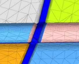
Mesh fusing
Fusing technology is enhanced to automate external aerodynamic modeling
process.
New options include "Create patch", "Fuse in tangent direction", and
"Make free edge connection". New options have also been added to
significantly reduce connection time for large models.
STL inputs are now supported to fuse. Figure 1.
BatchMeshing
Enhanced and simplified geometry cleanup
Geometry cleanup has been enhanced to provide flexibility,
consistency, and better feature capture.
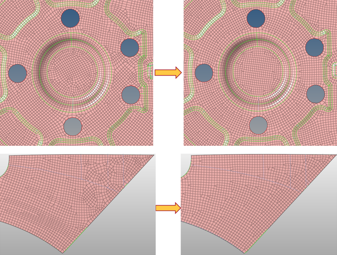
New options were added to the parameter file under Geometry
Cleanup. Control certain geometry cleanup steps before
midsurface extraction with the "Pre-Midsurface geometry
cleanup" option. Control suppression of feature edges based
on curvature break angle which leads to predictable and
improved feature capture with the "Flat feature suppression
level" option. Figure 2. . Flat feature suppression level set to Very
Low
Create meshes with fewer minimum element size quality
failures with the "Suppress edges by proximity" option. Figure 3. Suppress edges by proximity < 2.0
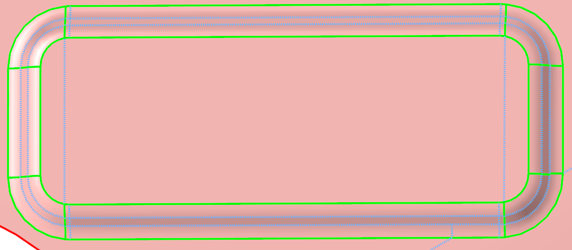
Control whether geometry trim lines are created when
adding washers around holes with the "Add circumferential
trim lines for washer" option.
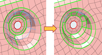
New and powerful mesh flow algorithm
The new mesh flow algorithm considers the shape of the
geometry and aligns the mesh to create orthogonal meshes,
reduces the number and strategic placement of trias, and
controls the average element size to provide a more uniform
mesh. Figure 4.
Improved parameter GUI highlight the changes
Bead, Logo and Thread recognition sections have been added
to provide ease of use and better understanding of
parameters based on feature.
The "Keep nodes on plateau feature top edges" option has
been renamed to "Allow nodes to move on plateau feature top
edges" to improve user understanding.
The following options were removed: Apply aggressive
stitching, Recognize main fillet strips and preserve main
edges, Recognize and preserve major feature edge, Mesh flow
align and size, Enable improved fillet mesh flow, Apply tria
reduction with minimum element size, Remove trias attached
to holes, Aggressive tria reduction, Apply failed features
cleanup and try to keep the shape of feature
Define CAD import options in Batchmesher
Defining CAD import options in Batchmesher overwrites those coming
from the .ini files or the default values, and applies
to all CAD files being imported. This enhancement allows
options to be locally defined without having to modify the
.ini files.
Generate direct midmesh
Generate a direct midmesh using Batchmesher. All options from the
Midmesh panel are available supported.
Midmesh
Drive resulting mesh with target and minimum element
size
Drive the resulting midmesh using the target and minimum
element size from the criteria file to enable the extraction
size to be given independent of the edge/feature cleanup
sizes. This also helps to eliminate unnecessary manual
cleanup steps downstream.
Performance improvements
Performance improvements of up to 40% for midmesh
creation.
Enhancements to the Edit Edge and Edit Face tools
Delete the 1D input loop and keep only free and non-manifold
edges with the "Delete 1Ds" option in the Fill Face tool.
Optionally keep boundary nodes locked to prevent disruption
of neighboring faces with the Align Faces tool. Imprint a
new geometry edge onto the midmesh with the "By geom edge"
option. Considered gaps/cracks along with intersections with
the "Detect intersections/gaps" option.
Continued robustness, performance and accuracy
improvements.
General improvements
Flattening option robustness.
Fillet edge capturing.
Input geometry edges not being imprinted.
Handling of rib ends so there are less intersections, less
cases left unimprinted, and so on.
Rebuild mesh
Rebuild mesh now supports shell elements associated with geometry to
allow remeshing results coming from Batchmesher, for example, to correct local
problem areas while still maintaining quality and flow.
A severe performance issue encountered when using rebuild mesh on a
small portion of a large model was improved. Further improvements are
also planned for future releases.
Map midmesh thickness
Linear interpolation support was added for nodal thicknesses.
Support for "Properties on components" assignment was extended to the
OptiStruct and Nastran solver interfaces.
Original components are now duplicated when using the "Properties on
components" option, in order to maintain relevant cards and
attributes.
The "Assign average thickness to element groups" option was enabled for
LS-DYNA and PAM-CRASH solver interfaces.
General performance and robustness improvements.
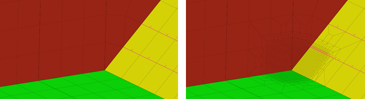
Automatic refinement (HyperWorks X only)
Automatically refine 1D and 2D elements with quad element transition
patterns using the brand-new Automatic refinement algorithm. This
algorithm is useful for refining around hot spot locations, and is
focused on aero and marine industry needs. Figure 5.
Refinement zone elements are selected as individual elements, or via
nodes which automatically select all adjacent elements. Transition zone
elements are automatically selected by a user-specified number of
adjacent layers. Figure 6.
Refinement zone elements are refined with the given refinement size, and
quad transition patterns are used to transition through the transition
zone to match the existing mesh. Both 2D and attached 1D elements are
refined.
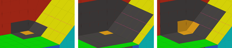
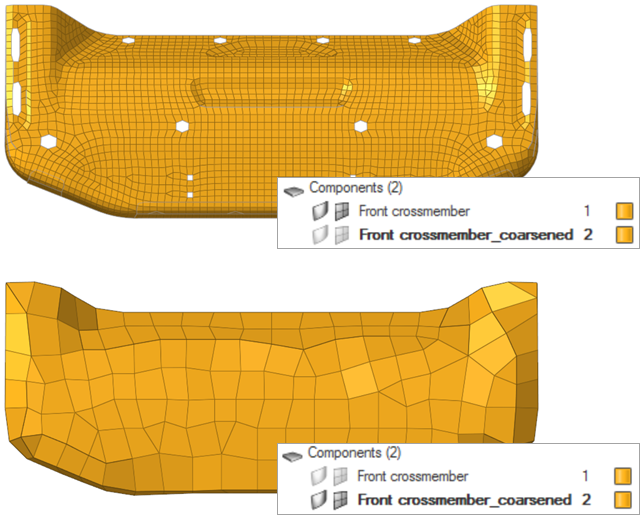
Mesh coarsening
Generate a new component containing the coarsened elements, and leave
the original component and its elements untouched with the "Retain input
mesh" option in the Coarsen Mesh tool. The coarsened elements will share
nodes with the original input mesh. Figure 7.
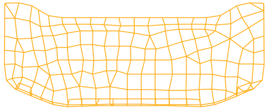
Create PLOTELs along all 2D element edges and delete the input 2D mesh
with the "Create PLOTELs along 2D edges" option. Figure 8.
If the "Convert coarsened 2Ds to PLOTEL3/4" option is also
enabled, then PLOTEL3/4 are also created. Figure 9.
Perform 1D coarsening with the *line_elem_decimator
command. Figure 10.
Performance and robustness improvements.
Surface deviation
Performance has been improved to make mesher competitive edge. Rouse of
surface meshing for complex models has improved, and the number of
meshing failures has significantly reduced. Mesh refinement performance
and sizes has also improved.
Adaptive tria remeshing
Performance for large remesh models has been improved to significantly
reduce the time it takes to remesh wrapped models. The robustness for
mesher has also been improved to avoid free edges, intersections.
Discrete topology input support and updates have also been added within
meshing.
Adaptive wrapper
Wrap geometry directly using topological selection.
Utilize regions for wrapping control setup.
Use metadata to do automation for wrapping.
Resolved Issues
Crashes and general instabilities with the Quality Index panel.
Robustness issues for the Rigid Body mesher and Feature mesh controls.
Issues with hole and gap filling for non-planar holes/gaps.
3D Meshing
New Features
Tetrameshing method
Lower memory utilization, enforce refinement, average and max-min size,
and create a smooth transition from surface using the new multi-threaded
meshing method added to the TetraMesher. This method also enables you to
control tetra growth from surfaces.
Model
Elements
Time
(minutes)
V 2017
V 2019
Headlamp model
6.4 mi
19
4
F1 car model
302 mi
367
146
Tetramesh updates for geometry modification
A new option has been added to update tetrahedral
mesh on geometric operations. You can automatically update tetrahedral
mesh associated with modified solid.
Fast operation as tetramesh is modified locally.
Supported operations include Surface offset, Solid Boolean, and Solid
trim with lines/plane.
Local tetrameshing controls
Define tetra mesh controls for individual solids using local
tetrameshing controls. You can define sizes or different meshing options
for individual solids. During volume meshing, locally defined volume
mesh settings will be enforced.
Topology based volume meshing
Volume Meshing mesh controls for tetrameshing can be defined for
geometric solids or surfaces.
Regions can be utilized for volume mesh control setup, and metadata can
be used to do a complete automation for surface meshing and volume
meshing.
Models do not need to organize in components for meshing setup.
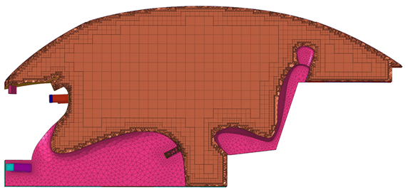
Hex/Octree dominant meshing
The Volume Meshing mesh control now supports Octree Dominant and Hex
Dominant core meshing options. You can define these options using the
"Core Mesh" attribute, accessed from the Mesh Controls Browser, Entity Editor. These options are integrated within
existing Volume Meshing controls setup, and can be used along with
boundary layers. Figure 11. . Resulting mesh when the Core Mesh attribute is set to Hex
Dominant.
Fix hexa element quality
Automatically check and fix the quality of hexa elements based on user
criteria using the Solid Mesh Optimization tool. With this tool you can
control maximum node movements allowed for quality fix, which reduces
the time spent fixing from ~2 hours per part (manual node movement) to
few a minutes.
Enhancements
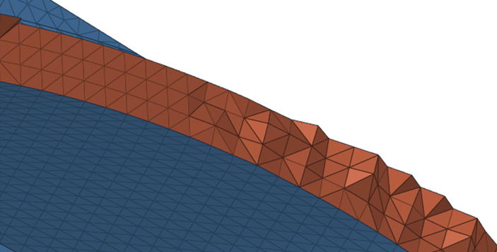
Layer tetra meshing
Robustness for layered tetra meshing has been enhanced.
Define the number of layers in the panels or from mesh controls.
Identify close proximity channels and fill in layers defined by
users. Figure 12. . Resulting meshing when Use Number of Layers is on and Number
of Layers is 3.
Boundary layer meshing
Boundary layer converge in close proximity areas has been improved.
When dealing with varying shell element sizes, meshing has been enhanced
to create a smoother boundary layer mesh.
Robustness for boundary layer imprint for complex shape input has also
been improved.
Miscellaneous
Elements can be offset directly from a 3D face.
Size change and Orthogonality quality check is available in the 3D
quality panel.
Resolved Issues
Tetra remeshing issues for shell update.
Issues with changing the element order during solid meshing.
Model Build and Assembly
New Features
Manage representations and revisions for part assemblies
Representation and revision management of part assemblies is now
supported. This facilitates usage of Part Browser
for use cases such as parts being connected by coincident nodes.
Concurrent usage of a library shared
Enhance concurrent usage of a library shared by multiple users with the
new library type powered by PostgreSQL.
Batch mode generation of part representations
Automated batch mode generation of part representations from a BOM input
is supported in the Part Browser. The output is a
HyperMesh binary file.
Library viewer
Browse the contents of a part library in the new library viewer.
Available representations are grouped per revision and can be seamlessly
loaded into the session.
Enhancements
Representation handling
The midsurface method can be selected prior to generating the common
representation. When saving representations, all rows for modifiable
columns can be selected via a keyboard shortcut.
Save As functionality
Save multiple parts across part assemblies using the "Save As" option
accessed in the Part Browser contextual menu.
Teamcenter visualization BOM support
The export of Teamcenter Visualization PLMXML’s is now supported with
the VizMockup BOM export file type.
Position parts
The "Scale" and "Position" options have been added to the Transform
tool.
Configuration management
When a part assembly is added to a part set or a configuration, a list
of child parts is displayed.
Part Assembly/Part solver deck comments
Part sets and configurations are written to the solver deck as
comments.
Resolved Issues
Part transformations are incorrect when the transformation matrix is
mentioned on CAD/Part.
Parts saved with shared surfaces results in disassociating shared
edges.
Crash and Safety
New Features
Simulate the positioning of a dummy
Dummy pre-simulation with the cable method can be performed using the
Dummy Pre-Simulation tool. With this tool you can export all of the
boundary conditions required to simulate the positioning of the dummy in
an input deck. Load simulation results in HyperMesh to update the dummy model.
Available in the LS-DYNA and Radioss solver interfaces.
Create a mechanism of the selected Finite Element model
Automatically extract bodies and joints to create a mechanism of the
selected Finite Element model using the Mechanism Extraction tool.
Enable a non-rectilinear translation motion between two bodies
Enable a non-rectilinear translation motion between two bodies by
creating a Cam joint entity in the Mechanism Browser.
Resolved Issues
Dummy information between *DUMMY_START and *DUMMY_END is empty when reading
an input deck.
Issue with moving a seat forward or backward when a dummy is linked to the
mechanism.
Positioning is occasionally incorrect when using the Pedestrian Impact tool
for head impactor contact point positioning.
When exporting input decks from the Mechanism Browser,
the Radioss /BEGIN card is not written
correctly.
Reading HyperMesh files and opening the Dummy Browser occasionally removes the dummy from the
display.
Conversion between Solver Formats
Enhancements
LS-DYNA to Radioss
conversion
*CONSTRAINED_JOINT_STIFFNESS_GENERALIZED converted to /SPRING
*CONSTRAINED_Extra_NODES_SET converted to
/RBODY,/GRNOD/GRNOD,/GRNOD/PART
*CONSTRAINED_JOINT_CYLINDRICAL converted to /SPRING,/PROP/KJOINT2/
property type 3
*CONSTRAINED_JOINT_REVOLUTE converted to /SPRING,/PROP/KJOINT2/ property
type 2
*CONSTRAINED_JOINT_SPHERICAL converted to /SPRING,/PROP/KJOINT2/
property type 1
*CONSTRAINED_JOINT_TRANSLATIONAL converted to SPRING elements,
/PROP/KJOINT2/ property type6
*MAT_VISCOELASTIC_OPTION/MAT_006 converted to /MAT/LAW42
*MAT_SPRING_GENERAL_NONLINEAR/MAT_S06 converted to /PROP/SPR_BEAM
*MAT_PLASTIC_KINEAMATIC converted to /MAT/LAW44
*MAT_DAMPER_VISCOUS converted to /SPING,/PROP/SPR_BEAM
*ELEMENT_BEAM_ORIENTATION converted to /BEAM,/SPRING
*ELEMENT_SEATBELT_ACCELEROMETER converted to
/ACCEL,/SKEW/MOV,/ADMAS
*RIGIDWAL GEOMETRIC,FLAT converted to /RWALL/PARAL
*RIGIDWAL GEOMETRIC,PRISM converted to /RWALL/PARAL
*RIGIDWAL GEOMETRIC,CYLINDER converted to /RWALL/CYL
*RIGIDWAL GEOMETRIC,SPHERE converted to /RWALL/SPHER
*DEFINE_TABLE converted to /TABLE
*DEFINE_CURVE converted to /FUNCT
*SET_NODE_ADD converted to /GRNOD/NODE
*SET_NODE_ADD_ADVANCED converted to /GRNOD/GRNOD
*SET_NODE_LIST converted to /GRNOD/GRNOD
*SET_NODE_GENERAL converted to /GRNOD/GRNOD
*SET_NODE_LIST_GENERATE converted to /GRNOD/GRNOD
Abaqus to OptiStruct conversion
*CONNECTOR SECTION conversion to JOINTG.
LINK to RROD
LINK ,ALIGN to RLINK,ORIENT
JOIN to BALL
JOIN,ROTATION to BALL, CARDAN
HINGE (JOIN + REVOLUTE) to REVOLUTE,BALL
SLOT to INLINE
CYLINDRICAL (SLOT + REVOLUTE) to INLINE+REVOLUTE
TRANSLATOR (SLOT + ALGIN) to INLINE,ORIENT
CARTESIAN to CARTESIAN
SLIDE-PLANE to INLINE
UJOINT, (JOIN + UNIVERSAL) to BALL,UNIVERSEL
HINGE to RBAR+REVOLUTE
*CONNECTORLOAD converted to LOADJG
*CONNECTORMOTION converted to MOTNJG
*DSLOAD (shell elements) converted to PLOAD2
*PLASTIC, HARDENING=COMBINED converted to MAT1/MATS1
*DYNAMIC, application=quasi-static converted to ANALYSIS=DTRAN
*MORIENT to NORM in CONTACT card when type is SLIDE and track option is
set to FINITE for discrete type N2S and S2S.
*RESTART, WRITE, OVERLAY to OS RESTARTW= 1 , COVER
*CONTACT OUTPUT to CONT(H3D)
*NODE PRINT, NSET = Preten_Nset,RF,CF,TF, to OS PRETBOLT(OPTI)=Yes
*INERTIA RELIEF to PARAM,INREL,-2
*PERTURBUTION steps are converted to linear steps
*FREQUENCY RESIDUAL=YES is converted to RESVEC=YES on conversion
Model Verification Director
Enhancements
Launching Model Verification Director
Launching the Model Verification Director no longer requires an
environment variable.
ProE/Creo
ProE/Creo and assembly data is now supported.
CPUs drawn
For one CPU or Multiple CPUs only 21 HWUs will be drawn.
Parameter to control location of .hm
file
Control the location of the .hm file after an offset function is executed with a new
parameter. By default, the .hm files will be saved under Report folder /
Offset_data_folder.
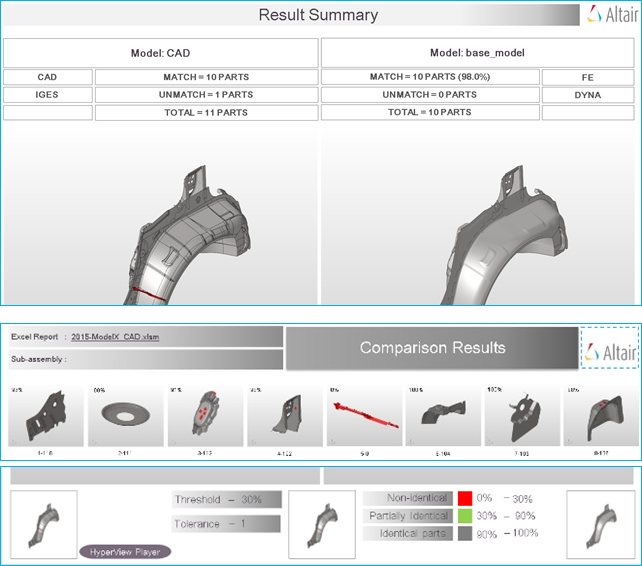
Performing comparison and verification check
Using respective browser Comparison and Verifications are executed.
Comparison checks
CAD / FE thickness are used as Tolerance for calculating match%.
Model Units and Position checks are added.
Skin, Plastic parts are supported when comparing CAD vs FE.
Report enhanced to accommodate Overlay view, Excel Report Link from a
PowerPoint file, Cumulative match% for variant model. Figure 13.
Match and Unmatched part colors are modified (Red,Blue =0% Match,
Green=30-90%, Grey=90-100%).
New options have been added to the result-review attribute to help you
review results for comparisons: tempComps, tempNodes, and
temComps+exportNodes (exports unmatched temp nodes to a
.txt
file).
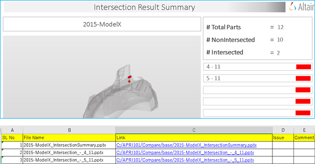
Intersection checks
A Part Revision check and Sub-system check has been added to check new
revision data and across two sub-systems
The Filter by Area and Filter by Bounding Box size options have been
added to skip checks small parts.
Filters can now be imported through CSV files. File name must contain
the filter type.
A new Parameter has been added to display 1D mode for Intersection. Figure 14.
PowerPoint and Excel summary reports are now supported in addition to
several other enhancements.
Spotweld check
The calculation method has been improved to support both CAD and
FEM.
The Intersection check find parts in the new intersecting plate between
the parts.
Surrounding Check was added to find parts that are near to the current
Spot weld.
A parameter to check all issues on all spot welds has been added.
Auto extraction of spot file from a CatProduct file is added to convert
circled x mark to vip file.
The 3D view displays a transparency view when the red spear is not
visible in any angle.
For the Reflect check, if the reflected location already has another
spot, an issue will not be reported.
Wide tolerance has been added to show surrounding parts for any flange
related issues.
Parallel-flange, if the offset is not done and both surfaces are at a
zero location, an issue will not be reported.
PowerPoint and Excel summary reports are now supported.
Connection check
New connection shape mismatch checks for TRIM parts have been added, and
use center line CAD as the input. New mismatch checks include:
arcweld-mismtach, seam-mismatch, hemming-mismtach, and
sealant-mismatch.
PowerPoint and Excel summary reports are now supported.
Spot comparison
PowerPoint and Excel summary reports are now supported.
Free Part check
Free Part check must exclude parts less than the minimum area set in the
configuration.
The Report layout is modified for the summary report.
Resolved Issues
Repeated Part set creation results in tcl error if threshold value is set
to1.0.
Batch mode for spot weld check does not work well.
Transformation matrix breaks for part instances.
Issue with solid tet support for comparison checks if a single file is
selected for the run.
Some connection checks are huge, and has been fixed by decreasing feature
angle.
Configuration user interface does not close if you do not have access to the
Altair Home directory.
Error received when exporting CSV file.
Issue with revision check on Catia data.
CAD and FE folders created by the tool are deleted if the delete-fefiles
option is on.
CAD Part Number is automatically renamed when a blank or special character
exist.
If Mat Vec comp is not found, no thickness needs to be assigned for the
CAD.
Config user interface must not stay on top of window, other window overrides
MVD user interface.
API
For a complete list of new, modified and deprecated APIs, refer to the API
Programmer’s Guide.
New Features
New entity types
New entity types have been added and mapped from old entities, which may
require scripting updates. Refer to the API Programmer’s Guide for more
details.
New checks for hm_getelemcheck*
The checks 'maxlength' and 'minlength' have been added for the
hm_getelemcheck* family of commands.
Detect flanges on both geometry and FE
Detect flanges on both geometry and FE with the
hm_flangedetection command.
Evaluating mesh patterns and connectivity
Evaluate mesh patterns and connectivity on an input quad/mixed mesh, and
output problem elements onto a mark with the
hm_detectmeshpatterns command. This is useful for
finding areas of a mesh that do not meet aesthetic requirements.
Perform model checking
A new suite of APIs has been added for performing model checking. These
may require scripting updates. Refer to the API Programmer’s Guide for
more details.
Resolved Issues
The hm_holedetection family of APIs causes a series of
crashes and general issues.
CAD and Solver Interfaces
Abaqus Interface
New Features
Parts and Instances
Parts and Instances format input files are supported for import and
export only without any modifications to the input file. The hierarchy
can be viewed in the Part Browser.
You can import an Abaqus Parts and Instances input file and export it in
the same format.
You can import an Abaqus Parts and Instances input file and export the
same as a flattened format input file.
Contact browser support
The Contact browser is now available in the Abaqus solver interface, and can be used for
auto-contact and detailed specification of contact conditions.
New Elements
New elements include: C3D8S, C3D8HS, C3D10S, C3D10HS, ITSUNI, ITSCYL,
CCL12, GK3D12M, GK3D12MN, GK3D18, GK3D18N
New keywords
New keywords are added for the coverage and some selective examples are:
*CLAY PLASTICITY, *BRITTLE FAILURE, *FILM PROPERTY, *FLUID CAVITY
behavior, *FABRIC material, *LOW DENSITY FOAM material, *COHESIVE
BEHAVIOR for debonding study, *BASE MOTION keywords for vibrational
studies
Enhancements
Support for CCL12 and Gasket elements
The Gasket element tool supports CCL12 elements, since CC12 elements
require mid-side nodes along the stack direction.
Show stack direction for solid face alignment
The stack direction is shown with an arrow once the direction has been
assigned in the Face Alignment tool.
*MODEL CHANGE enhancement
The *MODEL CHANGE keyword supports direct element definition along with
element sets.
Orientation review
Show the element system and material system for solid elements based on
the *DISTRIBUTION TABLE data in the Orientation review tool.
Updated Keywords
Keywords that have been updated to include new features with selective
examples include: *SELECT EIGENMODES for steady-state dynamics,
softening behavior for *CONNECTOR DAMAGE EVOLUTION, default integration
point for *SHELL SECTION, element deletion option in *SECTION CONTROLS,
additional support for *GEOSTATIC analysis set-up
Resolved Issues
Cannot contour loads such as pressure, film and so on for elements when
using the Contour Loads tool.
FBD tool in HyperMesh breaks due to ODB
reader.
When exporting *INITIAL CONDITION, datalines are not exported as
intended.
Issue with reading and exporting nested Include files.
Importing an Abaqus input deck into other solver
interfaces causes an application error.
Issue with element face selection using the Solid Face Alignment tool.
Cannot organize and map loads in the Loadsteps Browser.
Formula sets with negative increment creates floating point errors. The
starting and ending ID are now swapped from smaller to greater so that the
increment stays positive.
Model Checker for Abaqus cannot be accessed from
the Search tool.
The Face Selection panel disappears when creating *SURFACE.
Gasket elements surface are not recognized with face ID as SPOS/SNEG.
The original name for *DISTRIBUTION and *DISTRIBUTION TABLE are not
retrained upon import.
The dataline for *RIGID BODY keyword has unnecessary comma.
Clash with element flagging between C3D8S and CCl12 elements.
ELSET that are referenced in a *FASTENER is lost.
Acoustic elements AC3D15 and AC3D20 are lost in the standard 3D
profile.
AcuSolve Interface
All new features, enhancements, and resolved issues in the AcuSolve solver interface from 2017.2.4 and 2017.3 hotfix
versions are available in version 2019.
New Features
DENSITY_MODEL
New material density types include: Isentropic, Piecewise Linear, Cubic
Spline, and User Function.
SPECIFIC_HEAT_MODEL
New material specific heat types include: Piecewise Linear, Cubic
Spline, and User Function.
VISCOSITY_MODEL
Nw material viscosity types include: Ramped, Power Law, Bingham,
Carreau, Piecewise Linear, Cubic Spline, and User Function.
CONDUCTIVITY_MODEL
New material conductivity types include: Constant Prandtl Number,
Ramped, Piecewise Linear, Cubinc Spline, User Function, Constant
Anisotropic, Piecewise Linear Anisotropic, Cubic Spline Anisotropic, and
User Function Anisotropic.
GRAVITY, VOLUME_HEAT_SOURCE, MASS_HEAT_SOURCE
body_force commands support multiplier_function and user_function.
AUTO_WALL
The option auto_wall = ON/OFF is added to Wall boundary condition. This
option is hidden under Advanced Features, and is turned ON by default.
When auto_wall = on, mesh motion and reference frame related settings
need not be specified on the Wall boundary, and will not be accessible
under SIMPLE_BOUNDARY_CONDITION. The auto_wall feature can also be used
to model interface surfaces and internal surfaces. When auto_wall = ON,
SURFACE_OUTPUT commands are automatically generated by the solver.
Additional SURFACE_OUTPUT command is generated by modifying the default
output frequency settings.
THERMAL_SHELL
Model heat transfer through 2D thermal shells.
FAN_COMPONENT
Model flow through a radial or axial fan component via body forces
without the need for modeling a realistic fan geometry.
HEAT_EXCHANGER_COMPONENT
Model flow and heat transfer through a heat exchanger component.
ELEMENT_BOUNDARY_CONDITION
Specification of heat_flux, convective_heat_flux, and
radiation_heat_flux on Walls.
SURFACE_INTEGRATED_CONDITION
Specification of integrated boundary conditions for temperature and
mass_flux at Inflow and Outflow boundaries.
ELEMENT_OUTPUT
Output of quantities averaged over a volume of elements. This option is
available under each Volume component.
Discrete Ordinate Radiation Model
Model heat transfer effects due to participating media radiation using
Discrete Ordinate Model. This option is available under
PROBLEM_DESCRIPTION card.
Arbitrary Lagrangian Eulerian (ALE)
New mesh motion type under PROBLEM_DESCRIPTION card, which allows
arbitrary mesh motion. Useful for FSI applications.
Temperature Boundary Condition Type = None
Temperature BC at a Wall can be set to None under
Simple_Boundary_Condition. This is useful when advanced thermal BCs need
to be specified via Element_Boundary_Condition.
Reference Temperature Multiplier Function
Specification of Multiplier Function for Convective Heat Flux Reference
Temperature on a Wall.
Velocity Standard Deviation
Standard deviation of x/y/z velocity components are added to the types
of surface output quantities under
RESPONSE_VARIABLE.
Advanced Solver Settings
Access advanced settings for individual equation’s
STAGGER command (min/max number of stagger
iterations, linear solver iterations, projection and pressure projection
flags).
Inflow Velocity Type
Specify inflow velocity in cylindrical and spherical coordinate
systems.
Wall Velocity Type
Specify velocity of a moving wall in multiple ways - Cartesian,
Spherical, Cylindrical, Normal, and Zero.
Active Type
active_type is added to SIMPLE_BOUNDARY_CONDITION.
Used in applications with mesh motion.
Curve Fit Variables in NODAL_BOUNDARY_CONDITION
Additional variables are added under curve_fit_variable in
NODAL_BOUNDARY_CONDITION (x/y/z coordinate, reference coordinate).
GUIDE_SURFACE
Ability to specify a set of 2D elements as a guide for mesh motion.
FREE_SURFACE
Model a free surface by applying appropriate mesh motion boundary
conditions on the surface nodes.
Enhancements
Mixed Topology Export (VOLUME_SET and SURFACE_SET)
Option to export AcuSolve input file in a
new format. Mixed topology components containing multiple element
topology types (quad4/tria3, tetra4/hex8/pyramid5/penta6) are exported
as independent surface_sets and volume_sets, which are then referenced
under solver commands such as ELEMENT_SET,
SIMPLE_BOUNDARY_CONDITION, and so on.
NODAL_INITIAL_CONDITION
Set unique initial values per component or node set for each variable,
such as initial liquid volume fraction, or initial temperature. This is
useful in multiphase and heat transfer applications.
NODAL_BOUNDARY_CONDITION
Specify nodal boundary condition at individual nodes or node sets. This
is useful for setting reference pressure node in natural convection
applications.
Default Multiphase Materials
Default material models are readily available for use with Multiphase
Levelset approach (AirWater_Leveset_HM) and Multiphase Algebraic
Eulerian approach (AirWater_Eulerian_HM). These material models can be
used as a starting point to create other multiphase material
combinations.
AcuFieldView Launcher
AcuFieldView launcher has been added in two locations 1) Adjacent to
AcuSolve Job Launcher in the toolbar, 2) AcuSolve Controls > Tools tab after launching the simulation via AcuSolve Job
Launcher.
Component colors
New components of the same type are assigned unique colors when created
from the BCs > Components > CFD utility.
Known Issues
The following known issues will be addressed in a future release as we continuously
improve performance of the software:
New features added to the AcuSolve user profile are not currently supported
by the .inp reader. You should not import input decks
written from AcuConsole or from HyperMesh 2019.
Resolved Issues
Data type of Redistribution Factor under SOLAR_RADIATION_PARAMETERS card has
been changed from Integer to Real. This will require deleting and recreating
this global card when loading HM models created with 2017.2.4 and 2017.3
into v. 2019 or newer.
Mesh_Displacement_Type will be exported as “none” for all
SIMPLE_BOUNDARY_CONDITION cards when performing shape optimization
simulations (users need not do this manually).
Import bugs in the NODAL_INITIAL_CONDITION card.
Supervised Training data in DESIGN_VARIABLE does not accept duplicate
values.
CAD Interface
New Features
New CAD readers
Inventor 2018
Rhino (Windows only)
CATIA V5-R62018 (R28), V6 2015x
CREO 4.0 M020, 5.0
Inspire 2018.1
JT 10.2
NX 12.0 (both native and third-party readers)
Parasolid 30.0.185
SolidWorks 2018
New CAD writers
Inspire 2018.1
JT 10.2
Parasolid 30.0.185
Part and part assembly creation during CAD import
Parts and part assemblies are automatically created during CAD import to
allow for a more seamless and streamlined model build workflow, with
fewer steps and improved robustness.
Specify unit system during CAD import and export
Select a target unit system during CAD import and export to allow any
CAD file to be imported without requiring the user to know the unit
system defined in the incoming file.
Enhancements
Renamed Tribon reader
The Tribon reader has been renamed to AVEVA Marine.
Edit additional PDM attributes
The following PDM attributes can now be modified: PDM_MeshFlag, PDM_MID,
PDM_PID and PDM_Revision.
Read only assembly-level geometry
Read only assembly-level geometry contained within assembly files, which
helps when loading representations within the Part browser.
Read coordinate systems from NX files
Coordinate systems are optionally read from NX files via the native
reader.
Read infinite planes from CATIA files
Infinite planes are optionally read from CATIA files.
Support for JT ultra-lightweight precise (ULP) tessellations
Resolved Issues
Performance issues when importing STEP files containing many polylines.
Could not properly read JT assembly files with relative paths to children
parts.
Issues with general robustness and performance.
Exodus Interface
Resolved Issues
Issue with importing RBE2, RBE3 and ECHO cards.
Import mixed element type in one component is resolved by splitting to
elements into different blocks.
Issue with importing legacy models.
Performance issue during import and GUI creation of “Side Set”.
Solver Browser cleanup removed non-applicable items from
the browser.
FEKO Interface
New Features
New Feko solver interface
The Feko solver interface improves the
transfer of mesh element and material data between HyperMesh and Feko.
Allows for the efficient generation and modification of mesh elements
and the definition and modification of materials (called media in
Feko). The Feko solver interface guides you through the
process to create and edit such data in the format required by Feko.
Import and export of Feko mesh and media
data
The import and export of Feko mesh and
material data is supported through the import and export of the
*.fhm file format. This new file format
contains the mesh element data, the material definitions, and the
assignment of material properties to the mesh elements.
Supported mesh elements
HyperMesh
Feko
Bar2
Straight wire segments
Bar3
Curvilinear wire segments
Tria3
Flat triangles
Tria6
Curvilinear triangles
Tetra4
Tetrahedra
Supported Feko media definitions
Feko supports the definition and assignment
of several Feko medias.
The default Perfect electric conductor, Perfect magnetic conductor and
Free space media.
Finite conductivity Metallic media assigned to wire segments and surface
mesh triangles.
Isotropic Dielectric media, including optional magnetic properties,
assigned to surface mesh triangles (modeled with the SEP in Feko) and tetrahedral mesh elements (modeled with
the FEM in Feko).
LS-DYNA Interface
New Features
New LS-DYNA R9.0 solver interface
The LS-DYNA R9.0 solver interface is introduced
along with related major keyword updates.
New entity type for *ALE keywords
*ALE keywords are now treated as independent entities, whereas in the
past they were mapped to the Group entity type.
New entity type for *INTERFACE keywords
*INTERFACE keywords are now treated as independent entities, whereas in
the past they were mapped to the Group entity type.
New entity type for *TERMINATION keywords
*TERMINATION is a new keywords, and is treated as independent
entities.
New Keywords
An estimated 70 new keywords have been added, and are part of the
following LS-DYNA keyword groups: *CONTACT; *DATABASE; *ELEMENT;
*INTERFACE; *LOAD; *MAT; *PARAMETER; *SENSOR; *TERMINATION.
Support of *PARAMETER_LOCAL and *PARAMETER_EXPRESSION_LOCAL
LOCAL parameters are now available.
ID Parametrization
*PARAMETER has been extended to the parameterization of ID for the
LS-DYNA keywords created using Component,
Material, Property and Curve entities. The parametrization of the IDs
for those entities is also possible in any keywords where such entities
are referenced.
Mass Summary browser
View model mass, center of gravity, and inertia details in the Mass
Summary browser.
Enhancements
Updated keywords
An estimated 90 keywords have been updated, and are part of the
following LS-DYNA keywords groups: *ALE;
*CONSTRAINED_INTERPOLATION; *CONTACT; *CONTROL; *DATABASE; *ELEMENT;
*EOS; *INITIAL_VELOCITY; *INTERFACE; *LOAD; *MAT; *SECTION; *SENSOR
Penetration Check tool enhancements
The square edges contact option, activated by the SHLEDG or SRNDE
attributes is now considered in the Penetration Check Tool when this
option is enabled in the *CONTACT or *CONTROL_CONTACT keywords.
Model Checker enhancements
The Model Checker infrastructure and functionalities have been improved
for a better user experience.
New checks have also been added.
Removed Keyword 960 user profile
The Keyword960 user profile has been completely removed from the
installation.
Find entities attached to components
The Recursive option has been added in the Find Connectivity tool to
help isolate and find entities attached to selected components. This new
functionality will also help you to automatically find parts until all
connected parts are found.
Removed tool
The following tools, previously accessible in the Tools menu and Utility
browser, are now completely removed from HyperMesh: Set Browser, Create Part, Clone Part,
Material Table, Component Table.
Manage the printing of HyperBeam
messages
An import option has been added to enable or disable the printing of
HyperBeam messages. By default, this
option activated and HyperBeam messages are
not printed.
Export options enhancements
The Export option is now set to Custom by default in the Export
browser.
Resolved Issues
Issue with Model Checker checks related to property and material assignment
to the component, when *PART_COMPOSITE is used.
Reader issue when reading a deck containing
*CONTACT_AUTOMATIC_BEAM_TO_SURFACE.
Issue with reader behavior for the *DEFORMABLE_TO_RIGID keyword. It is also
updated to the R9.0 manual.
Parameter names were exported left justified, but are now exported and right
justified in the parameter name column. This change handles use cases in
which parameter names contain a blank, and the parameter is inside an
encrypted keyword.
Issue with head of edge vector values when creating an infinite plane
cross-section.
Selection of constrained nodal rigid body IDs was not allowed in the
*INITIAL_VELOCITY_RIGID_BODY keyword.
Material direction vectors for composite parts were not being displayed
correctly.
MARC Interface
Enhancements
Damping card support
The DAMPING solver damping card is now supported. This card can be
imported and exported, and can be accessed from materials.
Complex values in fixed displacements
Complex values in fixed displacement cards can be imported and exported.
Marc model files with displacements defined in real and imaginary phase
can now be imported and exported successfully.
Entity Editor support
The Entity Editor as now supported, and all Marc
solver entities can be accessed from the Entity Editor.
Nastran Interface
New Features
Generate 1D PLOTELs from DMIG grids
The PLOTEL from DMIG tool enables you to generate 1D PLOTELs from DMIG
grids. You can then use an exported solver deck with PLOTELs to
visualize DMIG in HyperView.
NX Nastran with comments written from FEMAP
The following formats are supported for FEMAP comments written to NX
Nastran models: $ Femap with NX Nastran Property: name and $ Femap Property:
name.
New keywords
New bulk cards include: NOLIN1, NOLIN2, NOLIN3, NOLIN4 and NLRGAP. These
can be referred in NONLINEAR subcase selection for transient response
analysis P2G, B2PP, M2PP and A2GG DMIG selection support.
Enhancements
Updated keywords
WR3R, WR4R and WRHR options in RSPINR card.
Imaginary values (9th field) for the DMIG matrix column entry is
supported.
Specify GRID DOFs for diagnostic request for structural grids can now be
defined in the SET card.
Create PARAM, CASE CONTROL and GLOBAL OUTPUT
Create PARAM, CASE CONTROL and GLOBAL OUTPUT in the Model Browser using the Create option in the right-click
context menu.
Manage DMIG
Review DMIG and visualize in spider form.
DMIG matrices names can now be written in multiple entries using one
case card.
Expand formula sets on import
The Expand formula sets on import option has been added to the Import
Browser.
BCPARA
The BCPARA card can be defined in the browser similar to BCONPRG.
BCONECT
The same BCONECT card can be referenced by different BCTABL1 cards.
BCONECT
The BCONECT card now allow the same BCBODY1 to be selected for the slave
and master.
Create sets based on PATRAN groups in decks
The Create sets based on PATRAN groups in deck solver option has been
added to the Import browser.
Export format export as a new solver
The Free format export as new solver option has been added to the Export
Browser.
New warning check
The warning, Loadcol has two or more different load types, has been
added to the Model Checker.
Performance improvements
Performance improvements of up to 70% when using the By HM
comments import option to import an input deck that
contains the direct property "HMDPRP".
Resolved Issues
All critical defects resolved in 2017 hotfixes are included in this
release.
Import issue of ACCEL I/O card with following form (SORT2,PHASE) = 1.
PBEAM cards that has extension lines with different HyperBeam comments is not read correctly.
Incorrect node ID is printed for for missing CP/CD.
1D element length does not consider offset value.
PSHELL and PSHEAR with the same ID do not stay the same on import.
Other critical defects have been resolved.
OptiStruct Interface
New Features
Generate 1D PLOTELs from DMIG grids
The PLOTEL from DMIG tool enables you to generate 1D PLOTELs from DMIG
grids. You can then use an exported solver deck with PLOTELs to
visualize DMIG in HyperView.
New entity type for Rigid Walls
RWALL keywords were originally mapped to the Group entity type, but
HyperMesh now treats those keywords as
an independent entity, with its own ID, icon, and graphics.
CQAXI element supports 4-node and 8-node quadrilateral axisymmetric
solid elements.
Enhancements
Updated keywords
NLADAPT, STABILIZ activates static stabilization in a nonlinear static
analysis.
CONTPRM, PREPRT,YES (default is NO) outputs Initial Contact condition in
ASCII filename.cpr file.
STOP and LOCK options for JOINTG (connector) can be specified on the
PJOINTG bulk entry.
OUTPUT, MATRIX,FULL, and OUTPUT,MATRIX,REDUCED write full or reduced
matrices.
Damping coefficient GE field added to PCOMP, PCOMPP and PCOMPG.
DUCTILE option added to CRITERIA in MATF card.
RADIAL defines draw direction in topology optimization.
Multi material topology optimization.
Non-Structural mass support for solid elements and properties.
Discrete design variables are available for the composite free-sizing
optimization PMDIS option in DSIZE card.
New response type FAILURE in dresp1 card.
ATTB=ZCF represents the Zero Crossing Frequency response based on the
RMS response.
ACMODL card has been enhanced with the ALLSET option.
ELSET option selects element sets in NSM1/NSML1/NSGE/NSGE1 cards.
SYSSETTING card enhanced with the RESVEC option.
NLPARM subcase selection in transient heat transfer subcase performs
nonlinear transient heat transfer analysis.
WR3R, WR4R and WRHR options in the RSPINR card.
SET card is enhanced with the subtype DMIG.
CIRCUL attribute was added to RTYPE BOREDST in DRESP1 card.
New option “Subcase mode tracking” added for frequency response type in
the DRESP1 card to differentiate subcase-based mode tracking.
HISTORY option added to FOS I/O card. This option is valid only when
Type=EVENT
FZTOSZ option enhanced with all supported fields in OUTPUT card.
DTPL card enhanced with OVERHANG continuation line.
AUTO option in DSIZE card for Automatic element grouping based on size
or number of elements in groups.
FKM correction method enhancements in FATPARM and MATFAT cards.
New response type powerflow FRFLOW in DRESP1 card.
SWLDPRM enhanced with the PATEXT option.
AUTO option to RIGID card in Global case control.
INT0 option added to the ISOP field in PSOLID property.
A/R flag indicates whether SN curve is based on amplitude or range in
the MATFAT card.
DOPTPRM, APPROX option is added with HIGH, MEDIUM, LOW, MEDIUM.
Segalman RMS von Mises stress and strain from random analysis as a
response in the DRESP1 card.
EIGRA/EIGRL cards are enhanced to support ALL option in the NORM
field.
CORNER option as solid stress response in ATTB for RTYPE STRESS in the
DRESP1 card.
SQNTL option is added to the FATEVNT card.
ASSIGN enhanced to read .dac and
.rpc files.
Sine sweep fatigue analysis support through the FATPARM and FATLOAD
cards.
New option added in DOPTPRM, MANTHR, threshold.
CGAP force is a response type in the DRESP1 card.
Contact pressure is added as a new response type in the DRESP1
card.
Topography design variable (DTPG) has been enhanced with Element-Set ID
to define local topography design regions.
Updated keywords - PARAM card
NLSNSINC triggers incremental sensitivity analysis for nonlinear static
subcases.
MVASPCON option to not apply autopsc to dof with damping.
MAXRATIO,value,ERROR/WARN
SHELLTI handles nodal shell thickness defined on the shell element
entries.
PRTMGG prints mass matrix in .mgg file.
ALLFT Multiple Failure Theory output is activated and all supported
failure theory output is calculated for the given model.
AMSE4EFM parameter controls the activation of the enforced motion static
solution in the AMSES solver in conjunction with the normal modes
calculation.
BUFFSIZE parameter defines the maximum size in 8 byte words of the
records of data written to the .op2 file.
ERPEAREA the ERP output is normalized with the total area.
OSTTSPRT One-Step Transient Thermal Stress Analysis solution and
convergence information is output in the .out
file.
TCLTINIT defines lower threshold values used for the HyperMesh command files.
TCLTSTEP defines step or interval values used for the HyperMesh command files.
ROMAX 4th field refers to the recovery matrix with YES being the
default.
REFPNT defines reference points for Inertia Relief at geometric center
of gravity or center of gravity of the model.
DDMNGRPS combine DDM and LDM.
The MMO , OP4DMIG and SIMPINP options were added to the ASSIGN
card.
FIXRBE3 automatically fixes invalid RBE3s.
PSDPRINC outputs maximum principal stress as a component in PSD/RMS
stress results.
PRTNORM option
Updated keywords - SYSETTNG card
RESVEC option controls the generation of extra global residual vectors
for Component Mode Synthesis (CMSMETH).
MAXRATIO=value, ERROR/WARN
UNKNDATA=WARN/ERROR based on user setting, posts warning or error
messages in .out file for unrecognized and
misspelled entries in the input deck.
IR4MECH option with YES/NO attributes for automatically support EIGRL
card for all the static subcases with SPCs.
Updated keywords - I/O cards
HDF5 format output request.
ESE card enhanced with Plastic, Neuber, and Group options.
H3D added as an output option in the GPFORCE output card.
THRESH/RTHRESH/RTOP/TOP options are supported for DAMAGE/LIFE/FOS
output.
PSDM option in STRESS output card was added for random response
results.
Create PARAM, CASE CONTROL and GLOBAL OUTPUT
Create PARAM, CASE CONTROL and GLOBAL OUTPUT from Model Browser using the Create option in the right-click
context menu.
Review DMIG
Review DMIG and visualize in spider form.
Ply orientation support for PCOMPLS property NLGEOM and IMPDYN analysis
types
The NLGEOM and IMPDYN analysis types are removed from the OptiStruct
solver interface. These analysis types can be activated using the
environment variable HM_ACTIVATE_NLGEOM_IMPDYN = YES.
Performance improvements
Performance improvements of up to 70% when using the By HM
comments import option to import an input deck that
contains the direct property "HMDPRP".
Resolved Issues
All critical defects resolved in 2017 hotfixes are included in this
release.
OptiStruct reader crashes due to embedded blanks
in PARAM cards.
When there are more than 7 panels to define RADSND, continuation cards are
created by HyperMesh, which causes an OptiStruct syntax error due to incorrect format.
STRESS TOP TOPN field is not exported properly.
Entity Editor does not show available SET_GRID when
defining SET_ID on DISP or PRESSURE output request cards.
Many other critical defects are resolved in this release.
PAM-CRASH 2G Interface
New Features
New PAM-CRASH 2017 solver version
Pamcrash2G2017 solver profile is introduced, and offers new keywords and
major keyword updates related to this new solver version.
New entity for SECFO keywords as Cross Sections
SECFO keywords were originally mapped to the Group entity type, but
HyperMesh now treats these keywords as
independent Cross Section entities with a unique ID, icon and
graphics.
Model Checker
The Model Checker tool has been added to the PAM-CRASH 2G solver interface, and offers
specific checks for solver validity categorized as ERROR, WARNING and
INFO.
New Keywords
An estimated 35 new keywords are added in HyperMesh 2019. These new keywords are part of
the following keywords categorises: PART, MATER, CNTAC, CONTROL,
Constraint, SENSOR, SECFO, ELEMENT, PYFUNC, BAGIN-CHAMBER sub-keywords.
Support of mapping files keywords
The IMPFIL, IMPORT and EXPORT mapping file keywords with sub-keyword
TRANSFORMATION can be created using the Position and Transformation
entities.
Support of picking definition keywords
The picking keywords PICEXP and PICIMP from 2015 onward and PICK in 2012
to 2014 user profiles can be created using the Position entity.
New Mass Summary browser
The Mass Summary browser was added to enable you to review model mass,
center of gravity, and inertia details.
Enhancements
Updated keywords
An estimated 130 keywords are updated in this new HyperMesh version. These keywords are part of the
following keywords categories: PART, MATER, CNTAC, CONTROL, CONSTRAINT,
SENSOR, SECFO, SAFETY, ELEMENT, PYVAR, FUNCT, PLOT-OUTPUT, BAGIN-CHAMBER
sub-keywords.
Accurate Mass Calculation
The mass calculation logic has been improved to match the solver
behavior, NSMAS and NSMAS2 accounted as nonstructural mass.
Pamcrash2G2010-2011 solver interface
The Pamcrash2G2010-2011 solver interface is removed, but is still
available in the installation; however, it will no longer be
maintained.
Removed tools
The following tools, previously accessible in the Tools menu and Utility
browser, are removed from HyperMesh: Set
Browser, Create Part, Clone Part, Material Table, Component Table.
Improved reading and evaluation of Python keywords
The reading and evaluation of the PYFUNC and PYVAR Python keyword's expressions and IDs have been
improved. Complex expressions are not editable in the HyperMesh session, and the expression is not
evaluated when its child variables are missing.
FUNCT enhancements
Function (FUNCT) supports reference of the python function keyword
PYFUNC when FUNTYP is EPYFUN.
Format of data output
Data output for all the keywords is right justified except for
sub-keyword strings.
Improved import messages
Improved import messages with the keywords CNTAC, MATER, Include files,
HyperBeam, Airbag sub keywords and so
on.
Removed obsolete keywords
Obsolete keywords such as RWALL_KIN_CHECK, ADAPT, SUBTA, SOLID4N, SPH
and data are unsupported upon import if present in input deck.
Removed obsolete SPH control card
Obsolete SPH control card are removed, and the equivalent SPCTRL is
available.
Resolved Issues
Keyword BELTS are mapped to elements instead of beam section collector when
using the Entity Editor to select IDNODs.
Unable to import models that contain Shell and Beam elements that have the
same element ID.
OTMCO supports multiple weight factor on GES when using the Entity Editor to update WEIGHT & DOFCOD.
Issues related to the creation of INCLU keyword from the Solver Browser.
Issues with importing/exporting old solver decks that have MATER &
SPRGBM keywords handled.
Issue exporting when GES data has mixed range and is listed under GROUP
keyword.
Issue with FE-Overwrite when working with GES data across keywords (example:
BAGIN & PREFA).
Issue with enabled option in Export browser to write HyperMesh comments into output files.
Permas Interface
Enhancements
Updated keywords
$INERTIA -CORIOLIS & ROTATION
NSET by ESET
$SURFACE GEO
$CONTLOAD
Resolved Issues
$SYSTEM and $COMPONENT card is imported by default.
$GEODAT SHELL properties are retained on export.
Node coordinates exported with double precision.
Model checker added to find entities with >40 characters.
$ELSYS RSYS supported for sets.
$SUPRESS DOFTYPE=DISP export issue.
RADIOSS Interface
New Features
New Keywords
An estimated 50 new keywords are added in this HyperMesh version and enhance the Radioss keywords support.
New entity type for Accelerometers
The /ACCEL keyword was originally mapped to the Sensor entity type, but
is now mapped to an independent entity, with its own IDs, icon and
graphics.
New entity type for Mass
The /ADMAS keyword was originally supported as elements, but is now
mapped to an independent entity, with its own IDs, icon and graphics. A
specific graphic review for /ADMAS/TYPE5 is also available to review the
nodal mass distribution. Along with this development, all /ADMAS types
are now supported in HyperMesh.
New entity type for Elements Clusters
/CLUSTER keywords are now supported in HyperMesh, and are mapped to an independent
entity, with its own IDs, icon and graphics.
New entity type for Failure Models
/FAIL keywords were originally mapped to the Property entity type, but
are now mapped to an independent entity, with its own IDs and icon.
New entity type for Optimization keywords
Optimization keywords are now supported in HyperMesh inside the Optimization browser, and
are treated as special entities. The optimization keywords are imported
and exported in the Radioss.radopt file.
New entity type for Rigid Walls
/RWALL keywords were originally mapped to the Group entity type, but are
now mapped to an independent entity, with its own IDs, icon and
graphics.
New entity type for Positions and Transformations
/TRANSFORM keywords were originally mapped to the System Collector
entity type, but are now mapped to an independent Transformation entity.
Additionally, the Position entity is introduced as a collector of the
Transformation entities that are applied to the same content.
Support of Submodels
//SUBMODEL keyword is now supported in HyperMesh. ID offsets rules and transformation
rules on submodels are also implemented. All sets of type SUBMODEL are
also supported.
Support of XELEM elements
/XELEM elements are newly implemented in this HyperMesh version.
Creating transformations and positions
Create Transformation and Position entities more seamlessly using the
Create and Edit Position/Transformation tool, which replaces the
previously existing Transformation Manager.
New Mass Summary browser
The Mass Summary browser was added to enable you to review model mass,
center of gravity, and inertia details.
Enhancements
Updated keywords
An estimated 40 keywords are updated regarding the latest 2017 and 2018
Radioss solver versions.
/BEGIN card enhancement
The definition of the unit systems in the /BEGIN card support has been
improved for a better user experience. The support of /BEGIN cards in
Include files is also improved.
/TH card enhancement
The definition of the output variables into /TH keywords is now given as
a list selection.
Material features added into compatible materials
Material features keywords (/EOS, /LEAK/MAT, /THERM_STRESS, /VISC/PRONY)
were originally mapped to the Property entity type, but the definition
of these keywords is now directly implemented into their compatible
material keywords using the Entity Editor.
Composites modeling enhancements
Composites modeling now supports the usage of the new Radioss composites keywords introduced into the
Radioss 2017 version.
Review SETs graphically
Improvements have been made for the review of SETs based on the type of
set. For example, a /GRNOD/PART will highlight the nodes of the referred
components instead of highlighting the components.
Accurate mass calculation
The mass calculation logic has been improved to match the solver
behavior.
Penetration check enhancements
The Penetration Check tool now enables you to check Radioss Interface TYPE24. Additional improvements
have also been made in the penetration’s calculation for second order
elements.
Model Checker enhancements
The Model Checker infrastructure and functionalities have been improved
for a better user experience.
New checks have also been added to the Model Checker.
Importing sets of subtype /SUBSET and /PART
Sets of subtype /SUBSET and /PART are not imported as a formula set when
all referenced subset or part IDs are positive.
Removed tools
The following tools, previously accessible in the Tools menu and Utility
browser, are removed from HyperMesh: Set
Browser, Create Part, Clone Part, Material Table, Component Table.
Tools that were once available in the Utility browser are moved into the
Tools menu.
Manage the printing of HyperBeam
messages
An import option has been added to enable or disable the printing of
HyperBeam messages. By default, this
option activated and HyperBeam messages are
not printed.
Find entities attached to components
The Recursive option has been added in the Find Connectivity tool to
help you isolate and find entities attached to selected components. This
new functionality will also help you to automatically find parts until
all connected parts are found.
Resolved Issues
Could not create or import multiple /FVMBAG/MODIF cards defined in the
engine file.
Could not read /MAT/LAW60 with a number of functions less than 5.
Sets of type GENE are created incorrectly in the Entity Editor.