Entity Editor
The Entity Editor enables you to quickly view and edit entities in a model and correctly setup solver information.
The Entity Editor can be accessed from the Model, Reference and Solver browsers. In the Model Browser, the following view modes are supported: Model, Include, Component, Property and Material. When accessing the Entity Editor from the Reference Browser, you will only be able to view your entity selection's corresponding data in a non-editable form.
The Entity Editor opens when you create new entities, as well
as duplicate, edit, or select single or multiple entities in the browser. To expand and collapse the Entity Editor, click  in the top, right-hand corner. To
adjust the height of the Entity Editor, drag
in the top, right-hand corner. To
adjust the height of the Entity Editor, drag  up and
down.
up and
down.
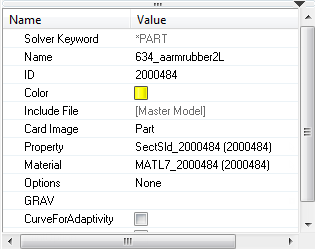
Figure 1.
Edit Multiple Entities
If you select multiple entities in the browser, the Entity Editor opens and displays the selected entities common corresponding data that can be modified simultaneously.
The rows that contain ### indicate that these fields do not contain common data but can still be modified. When you modify the data, both common and ambiguous, HyperMesh applies the changes to all of the selected entities.
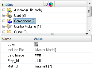
Figure 2.
Edit HyperMesh Specific Data
When you create an entity, it is assigned an unique ID, name and color. Use the Entity Editor to edit this data.
| Option | Description |
|---|---|
| Edit ID and name |
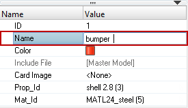 Figure 3. |
| Edit color |
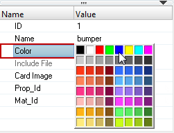 Figure 4. |
Edit Solver Specific Data (Template Data)
Every entity is assigned solver specific data, which you can modify using the Entity Editor.
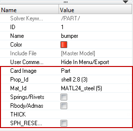
Figure 5.
Assign a Card Image
In the Entity Editor, you can assign a card image to an entity. The card images you are able to assign to an entity will depend on the user profile you have loaded and the entity type you have selected in the browser.
-
Select a new card image from the drop-down list.
The entity's card image changes, and the Entity Editor displays additional solver related fields.
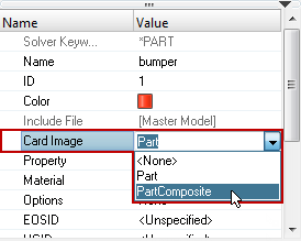
Figure 6.
Turn Fields ON or OFF
-
Turn fields on and off in the Entity Editor.
Option Description Turn field off Remove its corresponding value or select OFF from the drop-down list. If you hover over a field that is turned OFF, its default value will appear in the Value column.
Turn field on Enter a new value or select a value from the drop-down list. When a field is turned ON, its corresponding value will always be displayed in the Value column.
In the example below, assume that initially the field ISOP is turned OFF and has a default value of FULL. To turn the field ON, click its corresponding Value field and select a value from the drop-down list. If you want to turn the field OFF, select <OFF> from the drop-down list.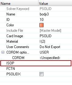
Figure 7. ISOP Field Off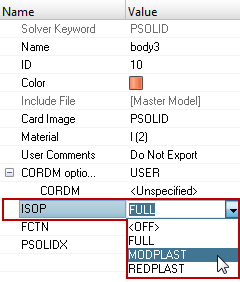
Figure 8. ISOP Field OnIn the example below, assume that initially the field G is turned OFF and has a default value of 80769.2. To turn the field ON, click the Value field and press Enter. To turn the field OFF, delete the value and press Enter. If you turn the field OFF, the Entity Editor will retain the previous value you specified.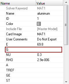
Figure 9. NU Field Off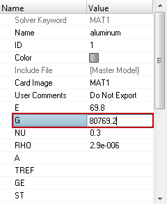
Figure 10. NU Field OnIn the example below, assume that initially the field MID4 is turned OFF. You can turn the field on and then assign it a material. To turn the field ON, click its corresponding Value field and select materials from the drop-down list. You can then click the yellow selector button and select a material to assign to the field. If you want to turn the field OFF, select <OFF> from the drop-down list.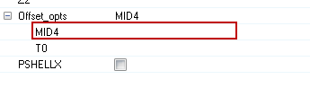
Figure 11. MID4 Field Off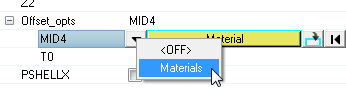
Figure 12. MID4 Field On -
Turn card image fields on and off in the Card Editor by clicking the field
heading.
When a field is turned ON, an additional field appears under the field heading, from which you can enter or select a value.
In example below, the card image MAT1 is displayed for a material in OptiStruct. By default, the field G is turned OFF. To turn the field ON, click its field header. The default value is displayed under the field heading.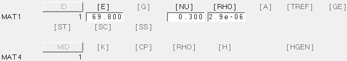
Figure 13. MAT1 Card Image with the Field G Off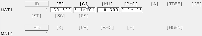
Figure 14. MAT1 Card Image with the Field G OnWhen defining data in tables, certain fields can be turned ON and OFF. To turn a field ON, right-click on the heading of the disabled field and select Status. In the image below, the NO field is being turned ON for the load collector TSTEP.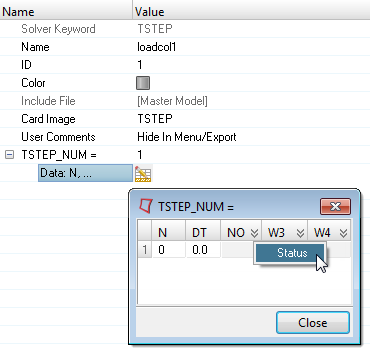
Figure 15.
Assign Entities
In the Entity Editor you can assign certain entities to another entity or a group of entities.
For example, you can assign a property to a component. When an entity has an entity assigned to it, the name and ID of the assigned entity will be displayed in the Value field. If an entity does not have an entity assigned to it, the Value field will display <Unspecified>.
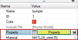
Figure 16.
In the Entity Editor, you can assign an entity using the Select dialog or the Entity Selector.
-
Method 1: Assign Entities Using the Select Dialog
-
Click the yellow selector.
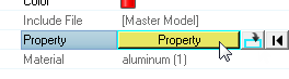
Figure 17. -
Select an entity in the following ways:
- In the Select dialog, select an entity.Tip: You can search for entities in the Select dialog by entering a name, ID, or card image in the search field. When you click
 or press
Enter, the dialog only
displays the entities that match your search
string.
or press
Enter, the dialog only
displays the entities that match your search
string.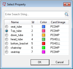
Figure 18. - In the graphics area, select an entity. HyperMesh automatically selects the entity in the
Select dialog.
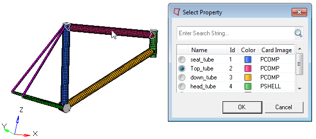
Figure 19.
- In the Select dialog, select an entity.
-
Click the yellow selector.
-
Method 2: Assign Entities Using the Entity Selector
-
Click
 .
.
-
In the panel area, click the yellow
selector.
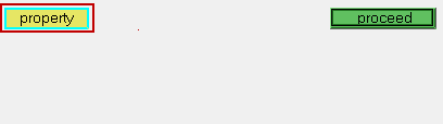
Figure 20. -
Select an entity in the following ways:
- In the panel area, select an entity and
click return.
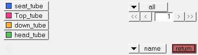
Figure 21. - In the graphics area, select a entity. HyperMesh outlines your selection in white.
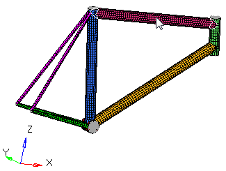
Figure 22.
- In the panel area, select an entity and
click return.
-
Click
Resolve Unresolved Entities
In the image below, the load collector Fatigue refers to a load collector with id=9, which is unresolved.
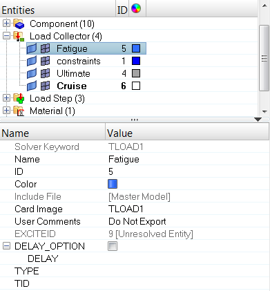
Figure 23.
- Right-click on the Name field of the unresolved entity and select Clear unresolved entity from the context menu.
- Click the entity's corresponding Value field.
- Click the yellow selector.
- In the Select dialog, select a new entity.
- Click OK.
Keyboard Shortcuts
| Function Key | Description |
|---|---|
| Tab | Moves from one row to the next in the Entity Editor. |
| Shift + Tab | Moves to the previous row in the Entity Editor. |
| Spacebar | Activates the Value field of the selected row. |
| Move up and down in the Entity Editor, a list of options in drop-down menus, or in a right-click context menu. | |
| Enter | Accepts the changes made to a parameter in the Value field, or selects an option in a right-click context menu. |
| Esc | Dismisses the changes made to a parameter in the Value field, or closes a right-click context menu. |
Create and Edit Assigned Entities
Create and Assign a New Entity
To create and assign a new entity to an entity or a group of entities:
-
Click Close.
The Entity Editor creates and assigns the new entity.
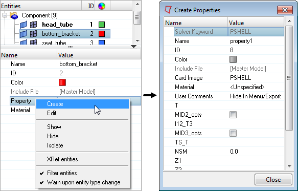
Figure 24.
Edit an Assigned Entity
To edit an entity that is assigned to an entity or a group of entities in the Entity Editor:
-
When you are finished making changes, click Close.
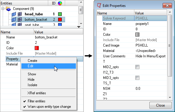
Figure 25.
Create and Assign Contact Surfaces Using Elements or Nodes
Only available in the Abaqus, ANSYS, and OptiStruct user profile.
-
In the Entity Editor, right-click on the Slave entity
or Master entity field and select Create Contact Surface using
Elements or Create Contact Surface using
Nodes from the context menu.
Note: The options available depend on the solver keyword selected.
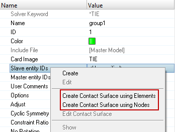
Figure 26.
Create and Edit Parameters
Create and Assign a New Parameter
In the LS-DYNA and Radioss user profiles, certain entities can be defined with parameters.
-
When you are finished defining the parameter, click
Close.
The Entity Editor creates and assigns the parameter to the selected entity.Note: These parameters can be used in HyperStudy for design exploration and optimization.
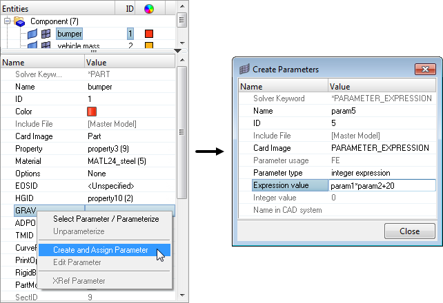
Figure 27.
Edit a Parameter
-
When you are finished making changes, click Close.
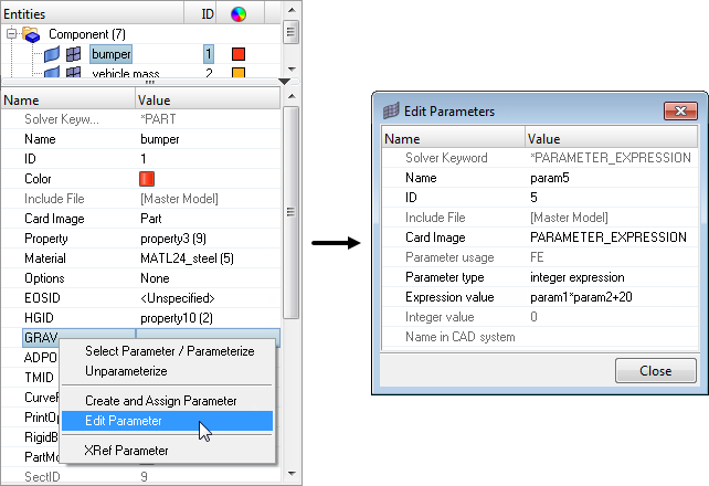
Figure 28.
Parameterize and Unparameterize Entities
Parameterize an Entity
-
Click OK.
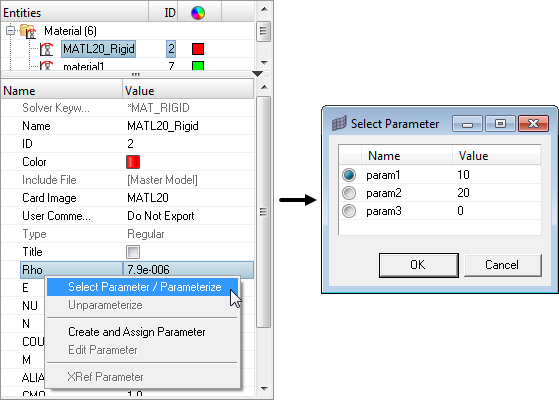
Figure 29. Parameter Rho is being Parameterized with the Parameter param1.
Unparameterize an Entity
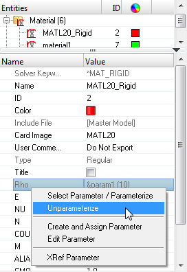
Figure 30. Parameter Rho is being Unparameterized with the Parameter param1.
Filter Entities
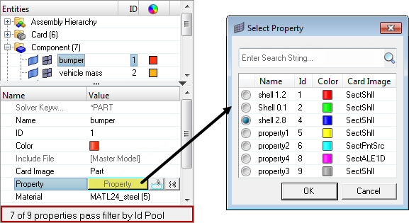
Figure 31.
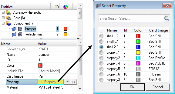
Figure 32.
Warn Upon Entity Type Change
-
To proceed, you must click Yes or
No.
By default, the Warn upon entity type change option is activated. If you do not want to display this message every time you make a change, you can deactivate this option.
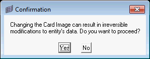
Figure 33.
View an ID List for Set Entities
Set entities are used to define and store lists of entity IDs for a specific entity.
Sets can be generated for nodes, elements, components, assemblies, properties, materials, ellipsoids, multibody planes, multibody joints, and multibodies which contain entity IDs for that specific entity. In the Entity Editor, you can view an ID list for set entities. The entity IDs are compacted using ranges, and segregated using ID pools. If some of the IDs are unresolved, than they will be listed separately under Unresolved IDs.
-
When you are finished, click Close.
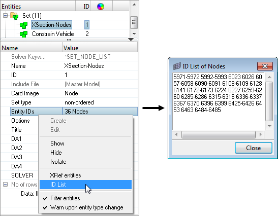
Figure 34.
View Xref Entities
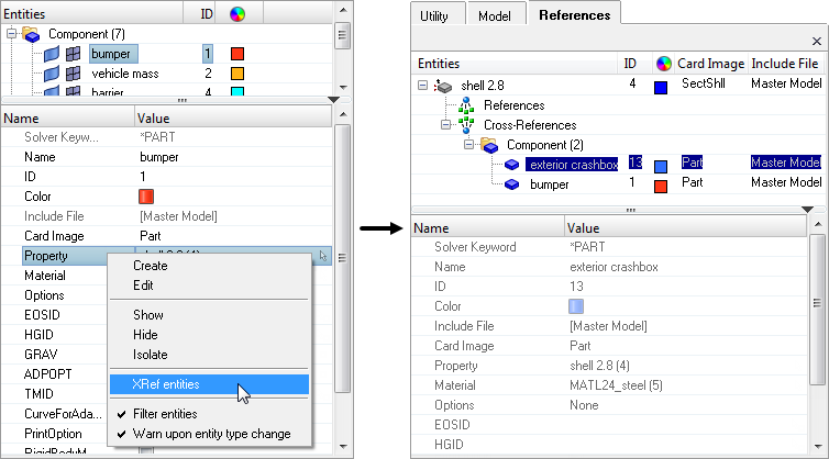
Figure 35.