Boat Ditching without Boundary Elements
The objective of this tutorial is to simulate Boat Ditching without Boundary Elements. So there is no boundary to represent continuous water. Basically, you are simulating Boat-Ditching in an enclosed volume.
In this model, the top chamber is air (including its outer layer) and the lower chamber is water (including its outer layer). Bi-Phase material LAW37 was used to model air and water. Boundary conditions are applied on each surface of boundary in the normal direction. An interface between fluid and boat (CEL) is defined to manage the contact.
Load the Radioss User Profile
- Launch HyperWorks Desktop.
-
From the Preferences menu, select User Profiles or click
the
 icon in toolbar.
- Select Radioss (Block140) and click OK.
Open the Model File
-
Click the Open Model icon
 to open the boat_ditching_2.hm file
you saved to your working directory from the radioss.zip
file.
to open the boat_ditching_2.hm file
you saved to your working directory from the radioss.zip
file.
Create and Assign a Material and Property to Air
-
Input the values, as shown below.
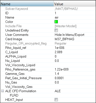
Figure 1.Note: Remember to select ALE under ALE CFD Formulation.
Create and Assign a Material and Property to Water
-
Input the values, as shown below.
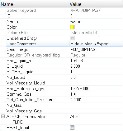
Figure 2.Note: Remember to select ALE under ALE CFD Formulation.
Create and Assign a Material and Property to Boat
-
Input the values, as shown below:
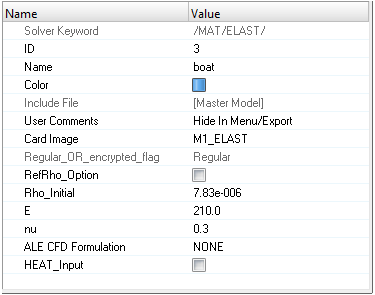
Figure 3. -
In the Model Browser, create a new property named
Boat with a Card Image of
P1_SHELL and assign the new property with the values
shown below:
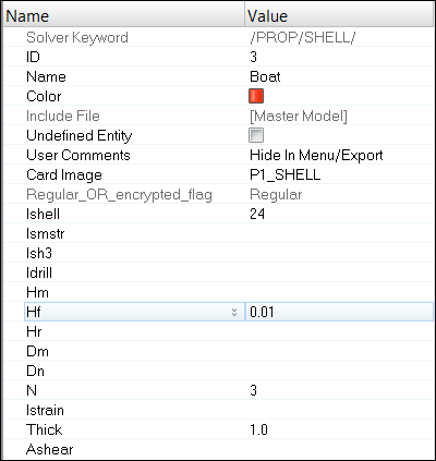
Figure 4.
Define an Interface between Boat and Water
-
Enter the parameter values, as shown below for Stfval and GAP.
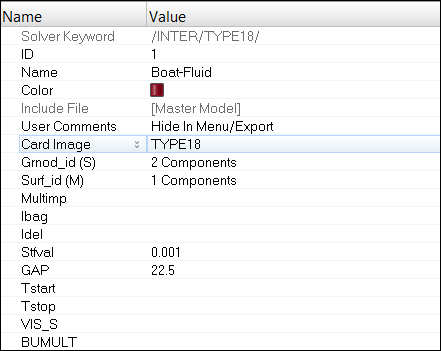
Figure 5.
Create an RBODY for the Boat and Assigning Mass
-
For Title, enter RIGID-BOAT, verify that Master node is
set to Calculate Node, set Slave node(s) to
Parts, and select the
Boat.
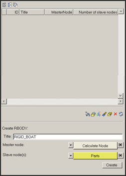
Figure 6. -
Select the created RBODY in the table and right-click and select
Edit card
 to
open the Card Image panel.
to
open the Card Image panel.
Create an Initial Velocity
-
Click Create to create the initial velocity boundary
condition.
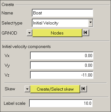
Figure 7.
Create the Boundary Conditions
-
Click the nodes selector and select By
face.
HyperMesh will automatically select nodes on the face, as shown in the figures.
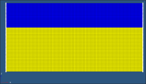
Figure 8.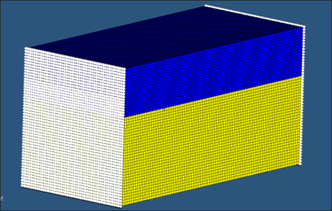
Figure 9.
Create Output Request and Control Cards
Export the Model
-
Click or click the Export icon
 .
.
-
Click the folder icon
 and navigate to the
destination directory where you want to export to.
and navigate to the
destination directory where you want to export to.
- For Name, enter boatditching_2 and click Save.
- Click the downward-pointing arrows next to Export options to expand the panel.
- Select Merge starter and engine file to export both the Starter and Engine file in one file.
- Click Export to export the file.
Run the Model in the Solver
- Go to .
- For Input file, browse to the exercise folder and select the file boatditching_2_0000.rad.
- Click Run.
Review the Results
The exercise is complete. Save your work to a HyperMesh file.