RD-T: 3510 Cantilever Beam with Bolt Pretensioner
This tutorial demonstrates how to simulate a simple cantilever problem with a concentrated load at the free end, using Dynamic Relaxation (/DYREL) method to obtain a static solution.
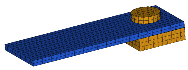
Figure 1.
Model Description
- UNITS: Length (mm), Time (ms), Mass (kg), Force (kN) and Stress (GPa)
-
Simulation time:
- CANTILEVER_0000.rad [0 - 25.1 ms]
- Steps to setup this model:
- Fix the Cantilever Beam to the support with a 10 kN pre-tension. The bolt attains 10 kN in 10 ms and remains constant thereafter.
- After pre-tension, a concentrated load of 0.2 kN is gradually applied at the free end of the beam from 10 ms to 25 ms and it remains constant thereafter.
- Material used:
Elasto-plastic material /MAT/LAW2.
[Rho_I] Initial density = 7.83e-6 Kg/mm3
[E] Young's modulus = 205 GPa
[nu] Poisson's ratio = 0.29
[a] Yield Stress = 0.792 GPa
[b] Hardening Parameter = 0.510 GPa
[n] Hardening Exponent = 0.26
[SIG_max] Maximum Stress = 0.95 GPa
[c] Strain rate coefficient = 0.014 GPa
[EPS_0] Reference strain rate = 1
Input file for this tutorial: CANTILEVER_0000.rad
Load the Radioss User Profile
- Launch HyperWorks Desktop.
-
From the Preferences menu, select User Profiles or click
the
 icon in toolbar.
- Select Radioss (Block140) and click OK.
Import the Model
-
Click or click
 .
.
-
Click the icon
 to open the CANTILEVER_0000.rad file you saved to your working directory from the
radioss.zip file.
to open the CANTILEVER_0000.rad file you saved to your working directory from the
radioss.zip file.
- Click Open.
- Click Import.
- Click Close to close the window.
Create a Rigid Body
-
Click the Mask icon
 in the
toolbar.
in the
toolbar.
-
In the modeling window, select one element from the
bolt.
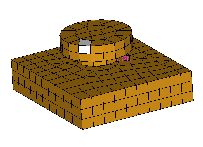
Figure 2. -
In the rigids panel, for primary node, select the node at the end of spring, as
shown in Figure 3, and for nodes 2-n, select the nodes, as shown in Fig 2.
Note: Be sure to set the selector to multiple nodes.
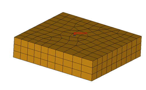
Figure 3.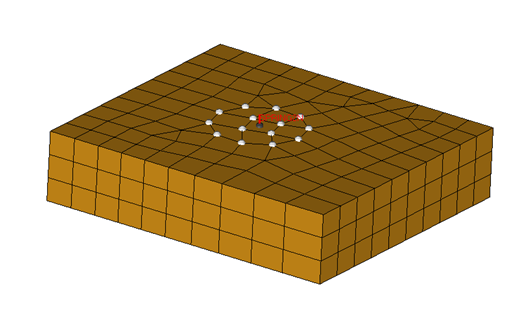
Figure 4. -
Click the Mask icon in the toolbar and click
reverse to show remaining elements of the bolt.
-
Use Steps 10 through 12 to create a rigid body with the nodes shown in the
following image with the other ends of the springs as the primary node and the
nodes on the bolts as slave nodes.
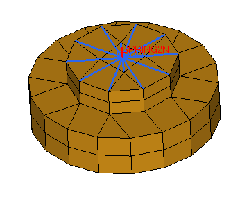
Figure 5.
Create and Assign the Material and Property to Plate and Support Bolts
- Enter the values, as shown below.
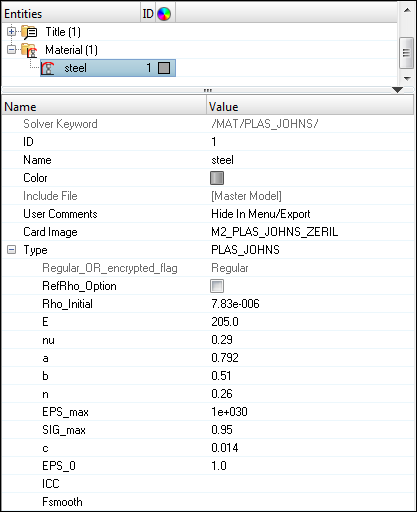
Figure 6.
Create and Update Pre-tensioner Spring Properties
- Fill in the other values, as shown below:
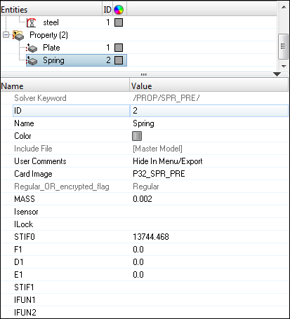
Figure 7. -
Fill in the values, as shown below.
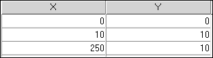
Figure 8.
Define Boundary Conditions
-
For Name, enter FIXED, set Select type to
Boundary Condition and set GRNOD to
Nodes.
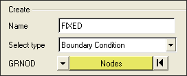
Figure 9. -
Choose the by window option and select the bottom layer
of the bolt support, as shown below.
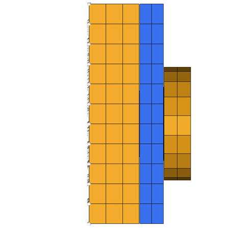
Figure 10.The selection should appear as shown below in the XY Plane view: - Fix all translational degrees of freedom.
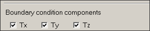
Figure 11.
Define the Load (CLOAD)
-
Using the by window option, select the nodes on the edge of the beam, as shown
below
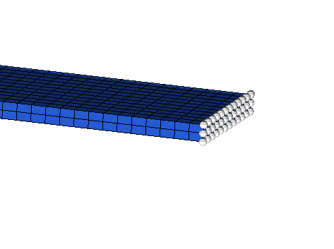
Figure 12.
Define Contact Interface between the Plate and Support Bolt
Create Time History
-
In the Entity Editor, set the name to
Deflection and select the nodes on the free end of
the cantilever, as shown in the following image:
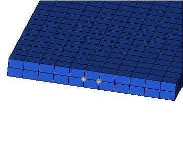
Figure 13. -
Set NUM_VARIABLES to 1 and click on the
Data:Var icon
 .
A table will open.
.
A table will open. -
Click edit and enter the variable name
DEF.
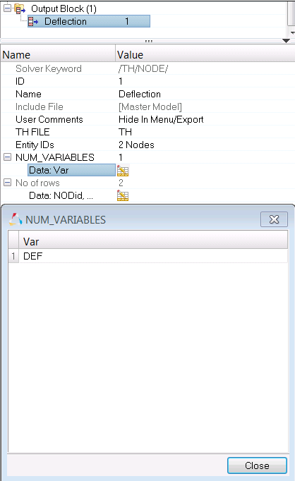
Figure 14.
Create Output Request and Control Cards
-
Input the values, as shown below:
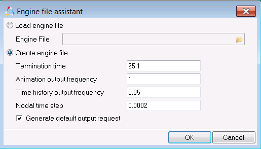
Figure 15.
Run the Model Checker
-
Click the Apply Auto Correction icon
 and click the
Run icon
and click the
Run icon  to auto-correct issues
within the model.
to auto-correct issues
within the model.
Export the Model
-
Click or click the Export icon
 .
.
-
Click the folder icon
 and navigate to the
destination directory where you want to export to.
and navigate to the
destination directory where you want to export to.
- For Name, enter CANTILEVER and click Save.
- Click the downward-pointing arrows next to Export options to expand the panel.
- Select Merge starter and engine file to export both the Starter and Engine file in one file.
- Click Export to export the file.
Run the Model in the Solver
-
Using HyperGraph, open the T01 file and plot the
deflection at the free end of the cantilever.
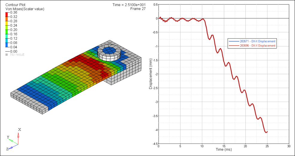
Figure 16.