RD-T: 3597 Cell Phone Drop Test
This tutorial demonstrates how to simulate a free fall of a cell phone due to gravity from a height of 1001mm using 2nd order tetra elements.
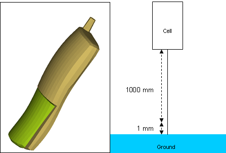
Figure 1.
Model Description
- UNITS: Length (mm), Time (s), Mass (ton), Force (N) and Stress (MPa)
- Simulation time: in Engine [0 - 3.3e-3]
- This is a very simple cell phone model used to demonstrate how to set up a drop test. The model is an assembly of two solid parts meshed with Tetra 10 elements, connected with spring elements, and contact defined between them.
- To reduce the simulation time, the cell phone is dropped 1 mm from the ground with an initial velocity of -4429.4469 mm/s representing the velocity that it would have attained from a free fall of 1000 mm.
- Boundary Conditions: Gravity load + initial velocity of -4429.4469 mm/s on the cell phone.
- Elasto-plastic Material /MAT/LAW36 (Plastic)
[Rho_I] Initial density = 1.16E-9 ton/mm3
[nu] Poisson's ratio = 0.3
[E] Young's modulus = 1000 MPa
| STRAIN | 0 | 16 |
| STRESS | 1 | 17 |
Load the Radioss User Profile
- Launch HyperWorks Desktop.
-
From the Preferences menu, select User Profiles or click
the
 icon in toolbar.
- Select Radioss (Block140) and click OK.
Open the Model File
-
Click the Open Model icon
 to open the cellphone.hm file
you saved to your working directory from the radioss.zip
file.
to open the cellphone.hm file
you saved to your working directory from the radioss.zip
file.
Create the Curve Material
-
Enter the X and Y coordinates, as shown below.
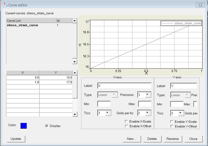
Figure 2.
Create and Assign the Material and Properties for Cell Phone Parts
- Input the values, as shown below.
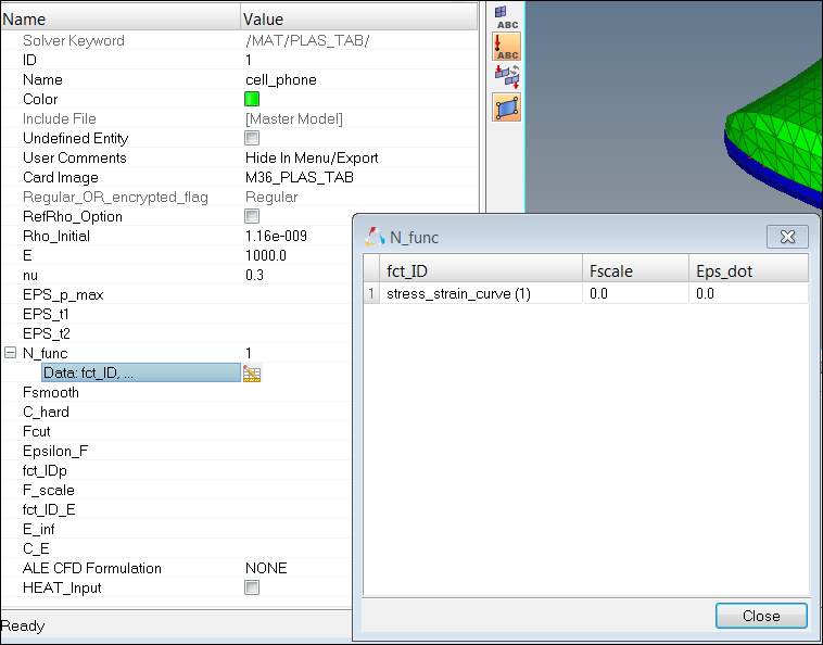
Figure 3. -
Set the variable I_tetra to a value of 1.
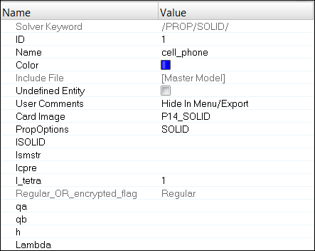
Figure 4.
Create the Property for Spring Links
Define the Interface between Cell Phone Parts
-
Set Gapmin to 0.3.
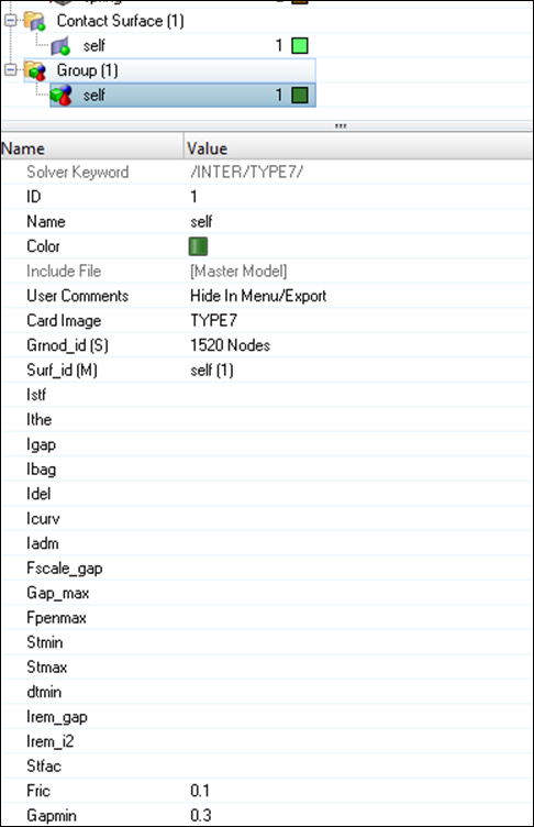
Figure 5.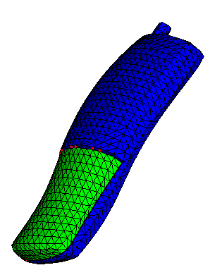
Figure 6.
Create a Rigid Wall
-
Make sure the normal vector is set to z-axis, as shown
below.
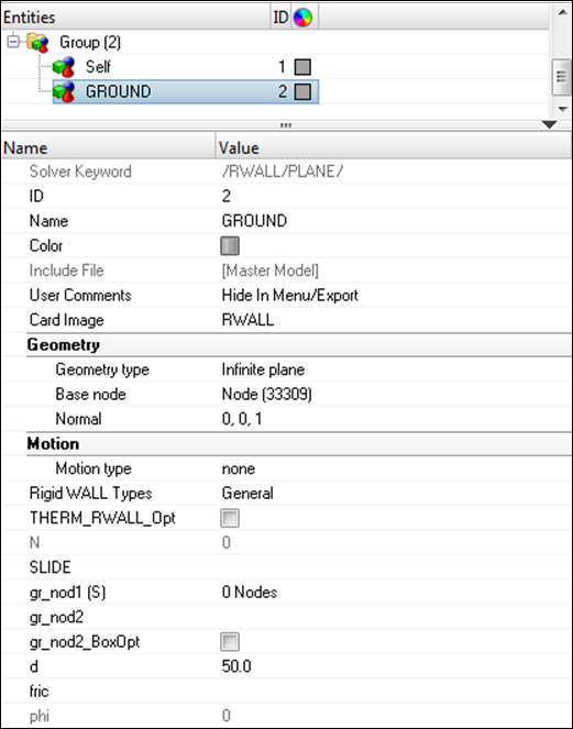
Figure 7. -
Right-click on GROUND and click
Review.
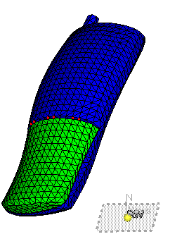
Figure 8.
Create a Gravity Load
-
Set scale_y to -9810.0 indicating gravity in opposite Z
direction.
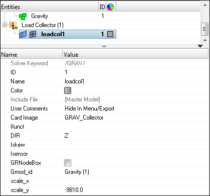
Figure 9. -
Enter X and Y, as shown in the following image:
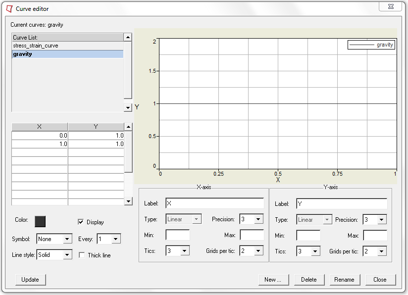
Figure 10.
Create an Initial Velocity
-
For Vz =, enter the value -4429.4469.
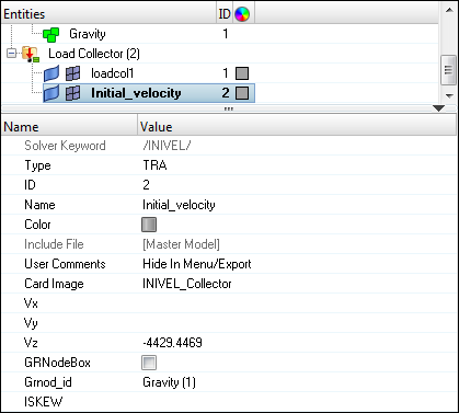
Figure 11.
Create Output Request and Control Cards
Export the Model
-
Click or click the Export icon
 .
.
-
Click the folder icon
 and navigate to the
destination directory where you want to export to.
and navigate to the
destination directory where you want to export to.
- For Name, enter Cellphone and click Save.
- Click the downward-pointing arrows next to Export options to expand the panel.
- Select Merge starter and engine file to export both the Starter and Engine file in one file.
- Click Export to export the file.
Run the Model in the Solver
- Go to .
- For Input file, browse to the exercise folder and select the file cellphone_0000.rad.
- Click Run.
Expected Results
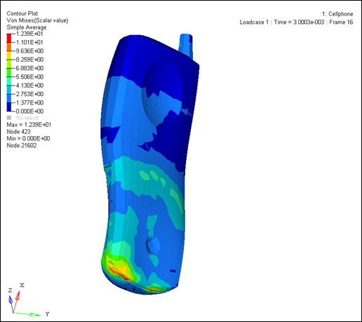
Figure 12. Von Mises Stress Contour (MPa)
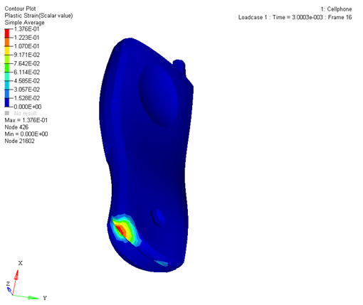
Figure 13. Plastic Strain (mm/mm)