RD-T: 3500 Tensile Test Setup
This tutorial demonstrates how to simulate a uniaxial tensile test using a quarter size mesh with symmetric boundary conditions.
The model is reduced to one-quarter of the total mesh with symmetric boundary
conditions to simulate the presence of the rest of the part.
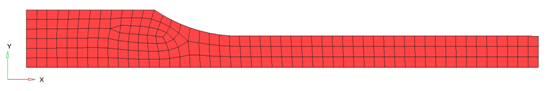
Figure 1.
Figure 1.
Model Description
- UNITS: Length (mm), Time (ms), Mass (kg), Force (kN) and Stress (GPa)
- Simulation time Rootname_0000.rad[0 - 10.]
- Boundary Conditions:
- The 3 upper right nodes (TX, RY, and RZ)
- The center node on left is totally fixed (TX, TY, Rx, RY, and RZ)
- A symmetry boundary condition on all bottom nodes (TY, Rx, and RZ)
- At the left side is applied a constant velocity = 1 mm/ms on -X direction.
- Tensile test object dimensions = 11 x 100 with a uniform thickness = 1.7 mm
Johnson-Cook elastic plastic material /MAT/PLAS_JOHNS (Aluminum 6063 T7)
[Rho_I] Initial density = 2.7e-6Kg/mm3
[E] Young's modulus = 60.4 GPa
[nu] Poisson's ratio = 0.33
[a] Yield Stress = 0.09026 GPa
[b] Hardening Parameter = 0.22313 GPa
[n] Hardening Exponent = 0.374618
[SIG_max] Maximum Stress = 0.175 GPa
[EPS_max] Failure Plastic Strain = 0.75
Input file for this tutorial: TENSILE_000.rad
Import the Model
-
Click or click
 .
.
-
Click the icon
 to open the TENSILE_0000.rad file you saved to your working directory from the
radioss.zip file.
to open the TENSILE_0000.rad file you saved to your working directory from the
radioss.zip file.
- Click Open.
- Click Import.
- Click Close to close the window.
Create the Material
-
Input the values, as shown in the following image in the Entity Editor.
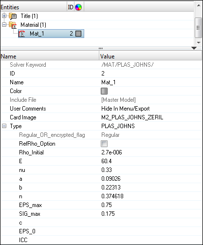
Figure 2.
Create the Property
-
For Thick, enter 1.7. in the Value field corresponding
to sheet thickness.
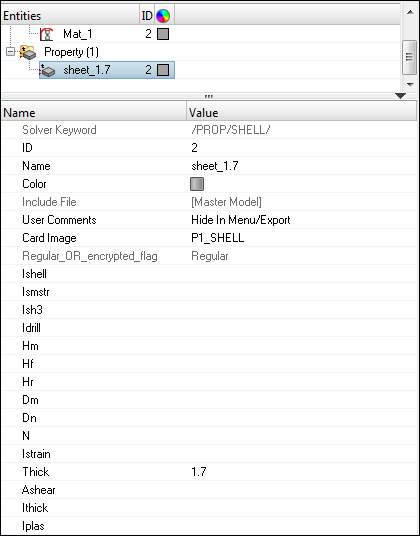
Figure 3.
Assign the Material and Property
-
Repeat steps 3 - 5 for Mat_Id and select Mat_1.
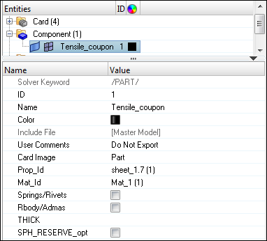
Figure 4.
Create the Boundary Conditions
-
For Name, enter constraint1, set Select type to
Boundary Condition and set GRNOD to
Nodes.
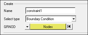
Figure 5. -
Select the three nodes as shown in the figure below and click
proceed.
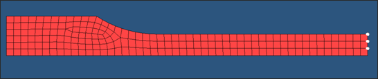
Figure 6. -
Select the node as shown in the image below.
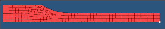
Figure 7. -
Fix degrees of freedom Tx, Ty,
Rx, Ry and
Rz.
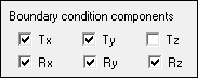
Figure 8. -
Select the nodes, as shown in the image below.
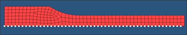
Figure 9.
Create the Imposed Velocity
-
Select the nodes, as shown in the image below.
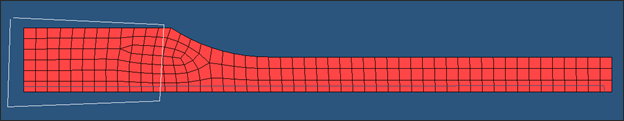
Figure 10. - Enter the values, as shown in table below.
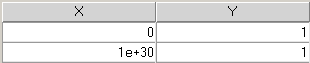
Figure 11.
Create Output Requests
- Input the values, as shown below:
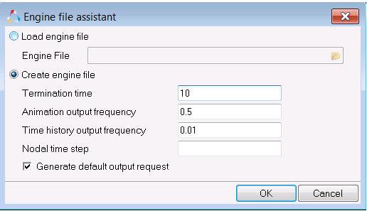
Figure 12.The tool generates typical output requests, such as stress, strain, velocity, etc.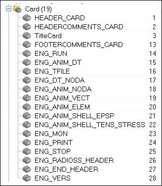
Figure 13.
Export the Model
-
From the File menu, click or click the Export Solver Deck icon
 .
.
-
For File, click the folder icon and navigate
to the destination directory where you want to export to.
-
Select Merge starter and engine file to export the
Engine and Starter file as one file.
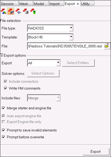
Figure 14. -
Click Run.
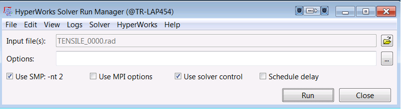
Figure 15.
Expected Results
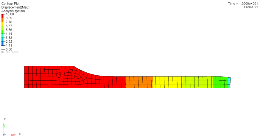
Figure 16. Total Displacement Contour (mm)
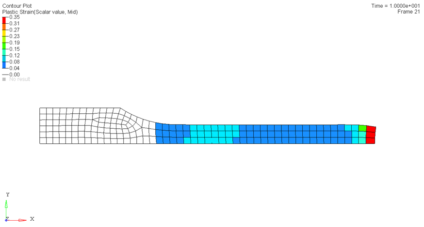
Figure 17. Plastic Strain Contour