RD-T: 3595 Three Point Bending with HyperMesh
This tutorial demonstrates how to set up 3-point bending model with symmetric boundary conditions in Y direction.
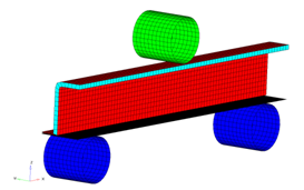
Figure 1.
Model Description
- UNITS: Length (mm), Time (s), Mass (ton), Force (N) and Stress (MPa)
- Simulation time: in Engine file [0 - 6.601e-002 s]
- Only one half of the model is modeled because it is symmetric.
- The supports are totally fixed. An imposed velocity of 1000 mm/s is applied on the Impactor in the (-Z) direction
- Model size = 370mm x 46.5mm x 159mm
- Honeycomb Material /MAT/LAW28: HONEYCOMB
[Rho_I] Initial density = 3.0e-10ton/mm3
[E11], [E22] and [E33] Young's modulus (Eij) = 200 MPa
[G11], [G22] and [G33] Shear modulus (Gij) = 150 MPa
- Elasto-Plastic Material /MAT/LAW36: Inner, Outer and Flat
[Rho_I] Initial density = 7.85-9ton/mm3
[E] Young's modulus = 210000 MPa
[nu] Poisson's ratio = 0.29
- Strain Curve:
0 1 2 3 4 5 6 7 8 9 STRAIN 0 0.012002 0.014003 0.018003 0.022002 0.026003 0.030006 0.032 0.033005 0.033523 STRESS 325 335.968 343783 349.245 358.649 372.309 383.925 388.109 389.292 389.506 - Elastic Material /MAT/PLAS_JOHNS: Impactor
[Rho_I] Initial density = 8e-9ton/mm3
[E] Young's modulus = 208000 MPa
[nu] Poisson's ratio = 0.29
Load the Radioss User Profile
- Launch HyperWorks Desktop.
-
From the Preferences menu, select User Profiles or click
the
 icon in toolbar.
- Select Radioss (Block140) and click OK.
Open the Model File
-
Click the Open Model icon
 to open the BENDING_0000.rad file
you saved to your working directory from the radioss.zip
file.
to open the BENDING_0000.rad file
you saved to your working directory from the radioss.zip
file.
Create and Assign the Material and Property for HCFOAM
- Input values, as shown below:
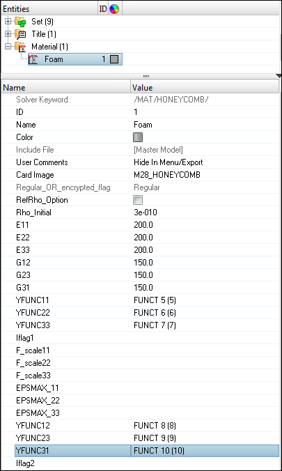
Figure 2.
Create and Assign the Material and Property for Inner
- Input the values, as shown below:
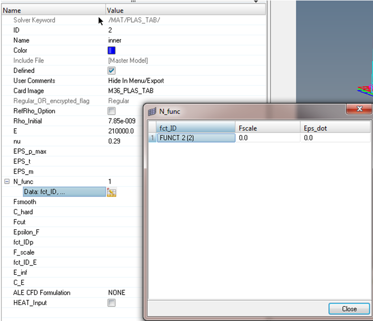
Figure 3.
Create and Assign the Material and Property for Outer
Create and Assign the Material and Property for Flat
Create and Assign the Material and Property for Impactor
- Input the values, as shown below:

Figure 4.
Create and Assign the Material and Property for Support
Create a Rigid Body for Impactor and Support
-
Similarly, create rigid body for Support component in a collector with the name
Support rigid using steps 1 to 12.

Figure 5.
Define the Imposed Velocity and Boundary Condition for the Impactor
-
Click nodes and select the master
node of the rigid body of the Impactor, as shown in the
following image.
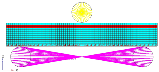
Figure 6. -
Click create to create the imposed velocity.

Figure 7.
Define the Fixed Boundary Condition for Support
-
Click create to create the boundary condition.
Figure 8.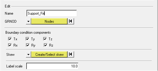
Figure 9.
Define the Symmetry Boundary Condition for Foam, Inner, Outer and Flat
-
Click create to create the boundary condition.

Figure 10.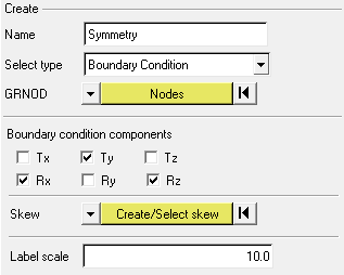
Figure 11.
Define the Contacts between Beam and Support
- Enter the values, as shown below:
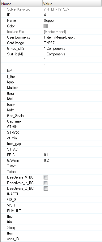
Figure 12. -
Similarly, create the contact for Impactor with Outer, as shown below.

Figure 13.
Define the Self Contact between the Beam Components
-
Verify that the interface has a Fric of 0.1 and Gapmin
of 0.2.
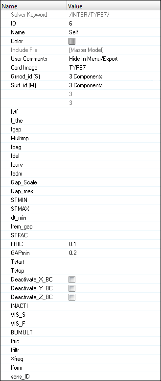
Figure 14.
Create the Interface Time History
-
Set NUM_VARIABLES to 1 and Data: Var to
DEF.
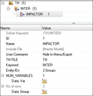
Figure 15.
Create Output Request and Control Cards
Export the Model
-
Click or click the Export icon
 .
.
-
Click the folder icon
 and navigate to the
destination directory where you want to export to.
and navigate to the
destination directory where you want to export to.
- For Name, enter 3BENDING and click Save.
- Click the downward-pointing arrows next to Export options to expand the panel.
- Select Merge starter and engine file to export both the Starter and Engine file in one file.
- Click Export to export the file.
Run the Model in the Solver
- Go to .
- For Input file, browse to the exercise folder and select the file 3PBENDING_0000.rad.
- Click Run.
Review the Results
- See if there are any warnings or errors in .out files.
- Using HyperView, plot the displacement, strain contour and vectors.