Fuse 2D Shell Meshes
Use the Fuse tool to connect close proximity, overlapping, and intersecting parts.
Fuse Open Shells
Use the Open Shells tool to automatically connect open shells to resolve penetrations/intersections, or prepare a BIW model for an electromagnetic analysis.
-
From the Elements ribbon, Edit tools, click .

Figure 1. - Optional:
On the guide bar, click
 to define fuse
options.
to define fuse
options.
Figure 2.
Tip: On the guide bar, click  to open the
Advanced Selection dialog, from which you can
filter geometry further by selecting a subset of entities based on
additional selection methods, such as By Component or By
Assembly.
to open the
Advanced Selection dialog, from which you can
filter geometry further by selecting a subset of entities based on
additional selection methods, such as By Component or By
Assembly.
Fuse Closed Shells
Use the Closed Shells tool to create watertight volumes for CFD and thermal applications with closed shells.
-
From the Elements ribbon, Edit tools, click .

Figure 3. - Optional:
On the guide bar, click to define fuse
options.
Figure 4.
Tip: On the guide bar, click to open the
Advanced Selection dialog, from which you can
filter geometry further by selecting a subset of entities based on
additional selection methods, such as By Component or By
Assembly.
Example: Fuse Mesh
The Fuse tool can be used with several types of analyses where mesh connections are required.
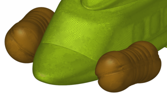
Figure 5. CFD Fluid Analysis Model Preparation. Create a water tight, fluid volume for CFD analysis by connecting shell and solid parts.
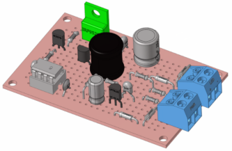
Figure 6. Thermal Analysis Model Preparation. Prepare the model for thermal analysis by connecting closed shells across the assembly.
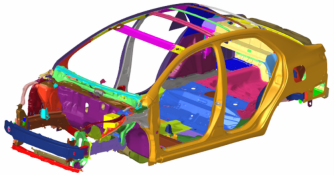
Figure 7. Electromagnetic Analysis Model Preparation. Define connections across part assemblies by connecting the midmesh of shell parts.
Fuse Options
Open Shells
- Fuse threshold
- Change fuse threshold.
- Remesh at connection
- Consider remesh at connection.
- Remove redundant patches
- Consider removing redundant patches.
- Redundant patch maximum width factor
- Change the redundant patch maximum width factor of fuse threshold value.
- Snap to features
- Consider snapping to features.
- Feature snapping tolerance factor
- Change feature snapping tolerance factor of fuse threshold value, within which the nodes positions resulting after the fusing of source and target elements can be snapped to features.
- Feature angle
- The maximum allowable break angle between adjacent elements.
- Fuse free edges only
- Fuse only free edges of the selected source and target.
- Bridge gaps
- Consider creating bridge elements between source and target.
- Projection type
- Select a type of projection from source to target.
- Remove target tails
- Consider to delete tails or small faces formed at the target after fusing source to target.
- Remove target tails tolerance factor
- Change the tolerance factor of fuse threshold value within which, if the width of the tail of the target tail face lies, it is removed.
Closed Shells
- Fuse threshold
- Change fuse threshold.
- Retain interface
- Consider retaining interface.
- Remesh at connection
- Consider remesh at connection.
- Collapse fusing patches
- Consider collapse fusing patches
- Maximum search angle
- Change maximum search angle.
- Fuse direction
- Change the fusing direction
- Number of layers
- Change number of layers.
- Feature angle
- The maximum allowable break angle between adjacent elements.
- Growth rate
- The factor to control the rate of transition in case of element size change.
Keyboard Shortcuts & Mouse Controls
| To do this | Press |
|---|---|
| Select shell components or elements | Left Mouse Click |
| Deselect components or elements | Shift + Left Mouse Click |
| Toggle between source and target | Tab |
| Exit tool | Esc |