Datasets
Vehicle Parameters
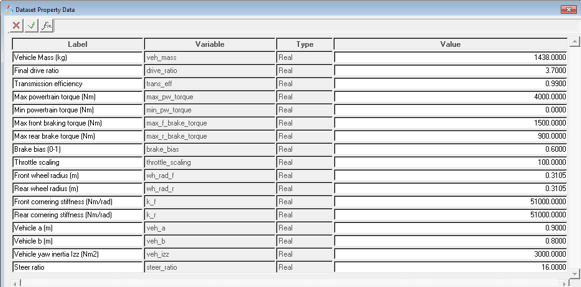
Figure 1.
| Parameter | Type | Range | Comments |
|---|---|---|---|
| Vehicle Mass | Real | Value>0 | |
| Final drive ratio | Real | Value>0 | Coupler ratio between drive coupler output and input shafts. Note that drive ratio is 3.7 in case of default RWD model and 1 in case of default FWD model. This value is not parameterized. |
| Transmission efficiency | Real | Value>0 | Input omega/(output omega*Drive ratio). |
| Drive type | Option | Value = FWD or RWD | Four wheel drive not allowed for advanced driver. |
| Max. powertrain torque | Real | Value > 0 | Torque produced by the powertrain at the input shaft of the differential at
100% throttle. *Required only for vehicle models without CSE powertrain. Driver can directly query CSE powertrain. |
| Min. Powertrain torque | Real | Torque produced by the powertrain at the input shaft of the differential at
0% throttle. *Required only for vehicle models without CSE powertrain. Driver can directly query CSE powertrain. |
|
| Maximum front braking torque | Real | Value>0 | Maximum braking torque on front axle at 100. |
| Maximum rear braking torque | Real | Value>0 | Maximum braking torque on rear axle. |
| Brake bias | Real | 0<Value<1 | Front to Rear. 0 is 100% front, 1 is 100% rear. |
| Front wheel radius | Real | Value>0 | Loaded radius |
| Rear wheel radius | Real | Value>0 | Loaded radius |
| Front cornering stiffness | Real | Value>0 | |
| Rear cornering stiffness | Real | Value>0 | |
| Vehicle a | Real | Value>0 | X component (Vehicle SAE system) of the distance from vehicle front axle to vehicle CG. |
| Vehicle b | Real | Value>0 | (Wheel base - vehicle a) |
| Vehicle yaw inertia | Real | Value>0 | |
| Steer ratio | Real | Value>0 | Ratio of steering wheel input to tire motion (toe). |
Analysis Settings
| Parameter | Type | Range | Comments |
|---|---|---|---|
| Altair Driver file | File | Address of the file path |
Signal Dimensions
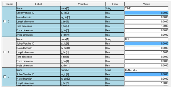
Figure 2.
$Example ADF end conditions block
(END_CONDITIONS)
 {SIGNAL      GROUP   ABS   OPERATOR   VALUE   TOLERANCE   WATCH_TIME}
  LONG_VEL      0      Y      SS        0.0      0.0001       1.50
  ROLL_ANGLE    1      Y      SS        0.0      0.0001       1.50
  PITCH_ANGLE   2      Y      SS        0.0      0.0001       1.50
  YAW_RATE      3      Y      SS        0.0      0.0001       1.50
  CG_Z          4      Y      SS        0.0      0.0001       1.50
$------------------------------------------------------------------------------------------------------------------
Using this block in ADF and signals dimension dataset, Driver will know the appropriate conversion factors for each and every value.
Control States
| MDL Statements | |
|---|---|
|
|
| gse_advanced_driver | Variable name of the driver cse. |
| “CSE Advanced Driver” | Label |
| 6 | Number of outputs. |
| sa_u_advanced_driver | Solver array with input signals. |
| Driver resizes the state array and sets initial conditions of the states internally. Hence, the state IC array should not be provided. | |
|
|
| USER | Indicates that Motionsolve should look outside its dll’s for the entry point. |
| USER({sa_par.idstring}) | Function call with par[0] = Array ID with vehicle parameters |
|
|
| 1 | The number of states are by default set to 1. |
|
|
| Msautoutils | Looks for this dll first in the current directory and then in MotionSolve installation. |
|
|
| SCRIPT_DRIVER | Entry point function name. |
Motions
| Steering wheel motion | Driver computes the required steering angle and applies motion to the steering wheel joint. |
| Front and rear wheel motion | Required to lock the wheels during static simulation and lock the wheels. |
| Differential motion | Required to lock the differential during static. |
Solver Arrays
| Mass Info Array |
|
| Brake Info Array |
|
| Tire Info Array |
|
| Drag Info Array |
|
| Driver Info |
|
| Drive Train Info Array |
...
*If gear index, i > Number of gears, N Gear Ratio [i] = Gear Ratio[N] |
| Bicycle Model Info Array |
|
| Vehicle Parameters Array |
|
| Input Signal Array |
Signal channel
|
| Control Entity Array List of motion ID’s and Joint ID’s passed to driver for deactivation after running static analysis |
|
Solver Variables
| Steer | Driver steer output -ARYVAL ( {driver_output_array_id }, 1 ) |
| Throttle | Driver throttle output ARYVAL ( {driver_output_array_id }, 2 |
| Brake | Driver brake output ARYVAL ( {driver_output_array_id }, 3 ) |
| Gear | Driver gear output ARYVAL ( {driver_output_array_id }, 4 ) |
| Clutch | Driver clutch output ARYVAL ( {driver_output_array_id }, 5 ) |
| Distance traveled by the vehicle | DIF ( {diff_dis_travel.id} ) |
| Longitudinal velocity wrt to gyro | -VX ( <Gyro fixed marker> , <Ground body CM marker> , < Gyro fixed marker > ) |
| Lateral velocity wrt gyro | VY ( <Gyro fixed marker> , <Ground body CM marker> , < Gyro fixed marker > ) |
| Yaw rate wrt gyro | WZ ( <Gyro fixed marker> , <Ground body CM marker> , < Gyro fixed marker > ) |
| Longitudinal acceleration wrt gyro | -ACCX( <Gyro fixed marker> , <Ground body CM marker> , < Gyro fixed marker > ) |
| Lateral acceleration wrt gyro | -ACCY( <Gyro fixed marker> , <Ground body CM marker> , < Gyro fixed marker > ) |
| Engine speed | Engine speed attachment |
| Longitudinal displacement | DX ( <Vehicle Body>) |
| Lateral displacement | DY ( <Vehicle Body>) |
| Vehicle heading angle | AZ ( <Vehicle Body>) |
| Simulation time | TIME |
| Roll Angle | AX(<Vehicle Body>) |
| Pitch Angle | AY(<Vehicle Body>) |
| Roll Rate | WX(<Vehicle Body>, <Ground Body>, <Vehicle Body>) |
| Pitch Rate | WY(<Vehicle Body>, <Ground Body>, <Vehicle Body>) |
Template
|
PLT file is generated at the end of the simulation. |
|
Writes out states of each and every component in the model. Default = ‘FALSE’ Slows down the simulation speed if switched on. |
|
CONSUB call to simulate transient and deactivate all the motions and joints after that. |
Sensors
| Maneuver switch | Switch to end one maneuver and start next maneuver. Sensor uses a sensor subroutine to monitor the signals and end conditions associated with the signal to actuate the switch. |