Driver Graphical User Interface
-
Click on the Altair driver analysis to bring up the Altair driver graphical
user interface.
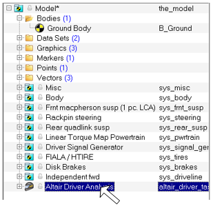
Figure 1.The corresponding panel is displayed. -
Provide the Altair Driver File, a driver script containing all the information
about the driving event required by the driver.
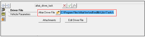
Figure 2. -
Click on the Edit Driver File button to open up the
Altair Driver File in the editor. The file editor colors the text with the
syntax of the Altair Driver File to make the script readable.
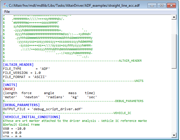
Figure 3. -
Click on the Attachments button to open the Altair
Driver Attachments dialog.
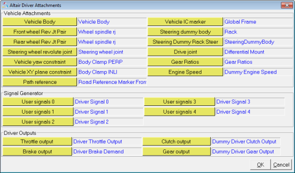
Figure 4.Attachments Vehicle Body Vehicle body *Required to calculate velocities, accelerations and position of the vehicle.
Front hub joint pair Joint pair of revolute joint between front hub and front spindle. *Required to lock the wheel joints to converge to correct equilibrium position after static.
Rear hub joint pair Joint pair of revolute joint between rear hub and rear spindle. *Required to lock the wheel joints to converge to correct equilibrium position after static.
Vehicle yaw constraint Perpendicular axes joint between vehicle body and the ground body. Vehicle XY plane constraint Inline joint between vehicle body and ground body. Aligning z axes of both ground and body. Thus, vehicle is bound to *Above two joints are required to constraint the vehicle from yawing and translating along XY plane while solving static.
Vehicle IC reference marker Marker with respect to whom the initial velocities are specified in the Altair driver file. Road reference marker Marker with respect to whom the user defined path, if any, is resolved. Drive joint Revolute joint between drive shaft and engine body fixed to the vehicle. *Required to lock the differential during static.
Engine Speed Solver variable from powertrain system that gives engine speed. Steering Dummy Body Dummy body (with negligible mass) in the steering system that connects to the Rack at Rack CG using an orientation joint and connects to rack housing using a translational joint at Rack CG. Steering Dummy Rack Steer Resolves to same dummy body for rack and pinion steering. Gear Ratio Curve Curve that informs driver about the gear ratios of the gear box if any. X(Gear) Y(Ratio) 0 0.00 (oth gear is ignored) 1 4.7 2 3 User Signals See the Signal Generator section for more details about the utility of these signals.
OL Signal 0 Driver signal 0 solver variable. OL Signal 1 Driver signal 1 solver variable. OL Signal 2 Driver signal 2 solver variable. OL Signal 3 Driver signal 3 solver variable. OL Signal 4 Driver signal 4 solver variable Driver Outputs Driver overrides the solver signals attached here with the appropriate outputs.
Example: The throttle signal attached here would be overridden with the throttle output of the driver.
Throttle Solver variable in vehicle model that driver uses to populate throttle output. Brake Solver variable in vehicle model that driver uses to populate brake output. Clutch Solver variable in vehicle model that driver uses to populate clutch output. *If the vehicle model does not have clutch, this attachment can be resolved to any unused solver variable. Clutch output from the driver will be strictly 0 in this case.
Gear Solver variable in vehicle model that driver uses to populate gear output. *Similar to clutch, gear output should be resolved to any unused solver variable in case it is not needed.
-
Click on the vehicle parameters tab to provide vehicle information required by
the closed loop controllers.
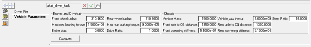
Figure 5.Vehicle parameters are needed by feedforward controllers to predict the states of the vehicle ahead in time. These vehicle parameters are required only if one of the feedforward controllers are being used. The internal models are anyways approximate and therefore, precise values are not required.Chassis Vehicle Mass In Kg *Required by Feedforward traction controller.
Vehicle Yaw Inertia In Kg m2 *Required by FeedForward steering controller.
Front axle to CG distance In m X component (Vehicle SAE system) of the distance from vehicle front axle to vehicle CG.
*Required by the feedforward steering controller.
Rear axle to CG distance In m X component (Vehicle SAE system) of the distance from vehicle front axle to vehicle CG.
*Required by the feedforward steering controller.
Steer ratio Steering wheel angle/Wheel angle *Required by the feedforward steering controller.
Tires Front wheel radius *Required by the feedforward traction controller. Rear wheel radius *Required by the feedforward traction controller. Front cornering stiffness *Required by the feedforward steering controller. Rear cornering stiffness *Required by the feedforward steering controller. Brakes Brake bias (forward) Front to Rear. 0 is 100% front, 1 is 100% rear. Max front braking torque Maximum braking torque produced at the front axle of the vehicle. Chassis Max rear braking torque Maximum braking torque produced at the rear axle of the vehicle. Powertrain Drive type Option: Front wheel drive or Rear wheel driver or Four wheel drive. *Required by the feedforward traction controller to calculate the driven wheel tire radius. In case of 4WD driven tire radius is averaged.
Driven tire radius =
(Front wheel radius +Rear wheel radius)/2
*Required by the feedforward straction controller.
Drive ratio Coupler ratio between drive coupler output and input shafts. Note that drive ratio is 3.7 in case of default RWD model and 1 in case of default FWD model. *Required by the feedforward traction controller.
Transmission efficiency Input omega/(output omega*Drive ratio) *Required by the feedforward steering controller.