What's New
View new features for MotionView 2019.
General
New Features
- Optimize Mechanisms with MotionSolve
- Multi-body systems can now be optimized directly through MotionSolve. The 2019 version comes with an optimization capability native to the solver, all within the MotionView environment. It uses MotionSolve’s Design Sensitivity Analysis (DSA) for calculating sensitivities for use in gradient based algorithms. This is coupled to SLSQP, a well known gradient based optimization algorithm.
- Topology Viewer
- MotionView 2019 can display the model in a schematic form to study the topological connectivity. The Topology View is available for Bodies, Joints, Bushings, SpringDampers, Forces and Beams. The topological connections can also be viewed at a system/assembly level or at the level of the entire model.
- For more information, see Topology View.
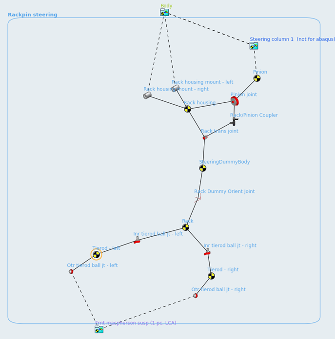
Figure 1. - Multi-Disciplinary Tools
- The new Multi-Disciplinary Tools can be used to help you easily build analytical models for certain sub-systems, such as cams and gears, along with other utilities that work across different application such as HyperMesh and HyperGraph.
Enhancements
- Calculate CG and inertias in the CG Inertia Summary tool
- The CG Inertia Summary now calculates CG and inertias in any general reference frame. CG can be calculated from any point, and inertias can be calculated at any point in the model.
- Import SLK files into the Data Summary tool
- The SLK file can be exported from the data summary, modified in an excel spreadsheet, and then re-imported. Expressions in the data (up to 255 characters) is also exported, thereby preserving the parametric relation between entities. An option to export evaluated values instead of expressions is also available.
- Ease of creation of system instance
- Using the Copy and Paste options, a new instance of a system can be easily created. The new instance shares the definition with the original instance from which it was copied. This functionality is applicable for all definition-based entities such as Analysis, Datasets and Templates. Any modification of the definition of the shared instance may break the sharing based on the Create a separate definition when modifying a shared instance settings access from .
- Default run directory
- A setting under for solver run files now offers the ability to specify a default folder for all solver runs. This information is stored in the model and will be available for subsequent model load.
- Interface node list file in Flexprep
- A list of interface nodes can be provided as a text file in the Flex Prep tool. The text file can contain the node numbers separated by commas or spaces. The node numbers can be spread among multiple lines.
- Flexbody damping ratio per mode
- Damping ratios can now be assigned to modes individually in the Flex Body – Modes dialog.
- Single RPC file from Fatigueprep
- By default, Fatigueprep hence forth will generate a single RPC file containing all channels. An option is available to create separate files per channel.
- Friction on universal joints
- An option to specify Both as a choice for Rotation constraints has been added for friction on universal joints. With this option, friction can be applied on both yokes simultaneously.
- Import contact entity in ADM
- A contact entity present in the ADM solver deck can now be imported as an equivalent contact entity.
Resolved Issues
- Export MDL Snapshot option in the Run panel is not saved in the MDL.
- CADGraphics – Changing the filename erases values set in the Location tab.
- Check Model does not compute correct number of degrees of freedom for flex bodies and NLFE bodies.
- Suspect data indicates bodies that derive properties from graphics with zero/negative mass.
- Colors from the ColorMaterial property list are not read correctly into MotionSolve XML.
- Changing an FEM file in the File Graphics results in distorted graphics.
- Data in the Curve panel is not retained when changing from values to File/math and back to values.
- Cut and paste of CADGraphics in a system results in an erroneous file path.
- Application hangs when archiving a model with Templates.
- Loads are not exported correctly for connections that have an origin at a Global Origin.
- Exporting a model containing entities that refer to deactivated entities does not result in an error.
- An error does not display when a connection refers to the same body.
- The option to write MAF during export saves into the MDL.
- Saving a model after changing a joint type that supports initial conditions (Cylindrical, Revolute, Translation) to a different joint type results in errors when opening the model.
- The Help button accessed from does not work.
- The max step size option in the Contacts panel, Advanced tab cannot accept values greater than 1.0.
MotionAuto
Highlights
- Support for building rounded section leaf springs and hockey stick leaf springs (non-planer).
- Leaf spring test event following SAE J510 test procedure.
- Fiala tire model enhanced with elliptical cam road contact model for better predicting durability loads.
- Full vehicle Drive Road Course Event with options for driving the vehicle along a straight path, a path read from the road property file, or a path defined by a curve in the model and at a constant speed or a speed profile defined by a curve in the model.
- Full-vehicle N-Post Event for ride and durability that includes spindle or tire coupled posts, and auxiliary posts for aerodynamic or other specialized inputs, and support for .dac and .rpc file inputs.
- Full-vehicle event reports with plots specific to the event, for example, lateral acceleration gain and phase for the swept-sinusoidal steer event.
Leaf Spring Builder
- Canvas view controls
- You can now pan, zoom, and fit the view of leaf shapes on the canvas in the Leaf Spring Builder. You can also save hard copies of the leaf shapes to a variety of graphic file formats including .jpeg, .png, and .pdf.
- Friction option added to Contact Properties
- The Friction option has been added to Contact Properties, which allows you to specify different coefficients of friction for different contacts. In previous releases, the friction properties you defined on the General tab were employed for all contacts.
- Enter loaded leaf shapes
- The Leaf Spring Builder now supports entering leaf shapes in the loaded, design position. Often CAD for vehicles shows the leaf springs in the loaded, design position rather than in a free position. To allow for easy creation of a leaf spring model from CAD data, the Leaf Spring Builder now supports the design shape condition. Once you enter the loaded leaf shapes and the axle loading, the Leaf Spring Builder will distribute the axle load among the leaves to produce a spring model that you can use directly in the vehicle.
- Points orient Leaf Spring Beam elements
- Beam elements are now oriented using MotionView points, allowing you to easily modify the shape of a leaf in MotionView by moving the points. In previous releases, beam elements were oriented using Euler angles. Changing the leaf shape in MotionView required you to modify the point locations and the beam Euler angles.
- Support for non-rectangular leaf sections
- You can now enter a radius for leaf spring cross-sections. The Leaf
Spring Builder considers the radius when computing the beam mass and
area moments of inertia Ixx, Iyy, and Izz. Using a non-zero radius will
have a lower mass and lower bending stiffness compared to a rectangular
section (radius = 0).
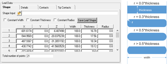
Figure 2. - New velocity output for leaf contacts
- The translational velocities used when calculating inter-leaf and tip liner contact forces are now output. In previous releases, only displacements were output. The F2, F3, and F4 channels are the X, Y, and Z displacement. The F6, F7, and F8 channels are the X, Y, and Z velocity. The Z direction is the normal contact force, while X and Y are the in plane directions for friction.
- Create inter-leaf contact between leaves that are not immediate neighbors
- Leaves that are not neighbors in the stack which overlap along the length of the spring with the potential for contact are now recognized, and appropriate interleaf contacts are created. In previous releases, overlap was not recognized.
- Build leaf springs when the spring seat is not parallel to the x-axis
- You can now build leaf spring models when the spring seat is not
parallel to the x-axis. In previous releases, the leaf shape data you
entered required the x-axis to be parallel to the spring seat where the
axle clamps to the spring. Once imported into MotionView, you then
rotated the leaf-spring, so the spring seat was not parallel to the
x-axis. This was inconvenient when, for example, your leaf shape data
was in vehicle coordinates and the spring seat was not parallel to the
vehicle’s longitudinal axis.
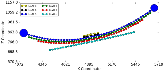
Figure 3. - Contact properties parametric to datasets in the leaf spring system
- In previous releases, if you had leaf spring system loaded in MotionView and wanted to change the contact properties, you had to edit the contact properties for every contact or return to the Leaf Spring Builder and modify the properties, and then rebuild the leaf spring system.
- Build hockey-stick style leaf springs
- You can now build leaf springs with non-planner leaf shapes, commonly known as hockey-stick-style leaf springs. The leaf spring builder now accepts x, y, z coordinates as input for leaf shape points.
- Locate leaves using reference markers
- Each leaf of the spring is now located by a reference marker in the parent MotionView leaf spring system. Moving the reference marker enables you to move the entire leaf.
- Distribute inter-leaf contacts equally to the front and rear
- You can now create inter-leaf contacts that are distributed equally to the front and rear of the axle. In previous releases, you had to switch contacts from front to rear to place contacts at the rear of the axle.
- Select leaf tip contact properties
- You can now select contact properties for leaf tip contacts. The Leaf Builder automatically creates non-master-leaves for leaf contacts, and previously used default Metal-Metal contact properties. The interface now supports selecting any contact properties the leaf property file contains.
- Test using SAE J510 procedure
- Simulating the SAE J510 test procedure is now supported. In the SAE J510 test the shackle is removed, the spring is inverted with the eyes facing downward, and was supported vertically but allowed to spread. Vertical force is applied at the spring seat via a fixture to stroke the spring and the force deflection curve recorded.
- In the Leaf Spring Builder, gravity is inverted instead of inverting the
spring.
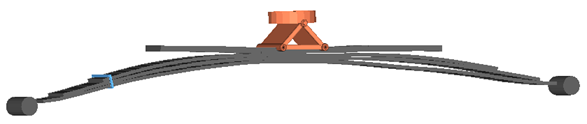
Figure 4.
Full Vehicle Events
- nPost Shaker event
- An nPost Shaker event can now be added to any vehicle. Posts can be coupled directly to the spindles or via spring-dampers to model tire stiffness. Input force or displacement signals can be obtained from .dac, .rsp, .rpc, or .csv files to the posts, and simulate the vehicle’s response to the input to assess vehicle ride or component loads.
- For more information, see n-Post
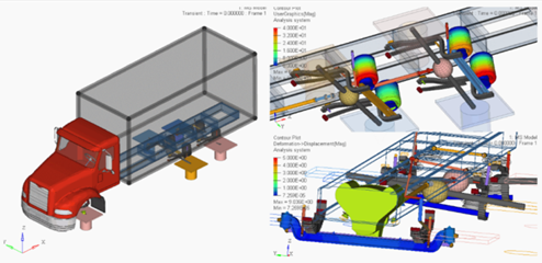
Figure 5. - Road Course Drive event
- Use the Road Course Drive event to simulate a vehicle driving on a road of your choice and assess vehicle dynamics, ride, or loads. You can select the road to drive the vehicle over, a path for the vehicle to follow, and a velocity profile which may be constant or specified by a curve of speed verses distance traveled.
- Event specific reports
- The View Report option has been added to enable you to generate a report for each full vehicle event that consists of plots and an animation for the event.
- For more information, see View Reports.
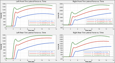
Figure 6. Event Report with Plots for Multiple Simulations
Enveloping Tire Contact
- FIALA Tire model enhanced with Elliptical Cam Contact model
- The FIALA tire model now supports an Elliptical Cam Contact model. The Contact model is based on the Elliptical Cam Contact method described in Pacejka’s Tire & Vehicle Dynamics Book. 3rd Edition (ISBN 978-0-08-097016-5).
- For more information, see Elliptical Cam Contact
Model.
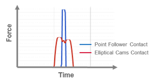
Figure 7. Point Follower Contact vs. Elliptical Cams Contact
Vehicle Library (MDLLIB)
- MDLLIB tire system now uses autoTire system definition
- When you build a passenger car or light truck using the assembly wizard,
the tire system included in the model uses autoTire systems for the
front and rear tires. Using the autoTire system enables you to use
MF-TYRE/MF-SWIFT, CDTire, FTIRE, or FIALA tire models without having to
replace the tire system. Note: Options for selecting the kind of tire system are removed from the assembly wizard.
- Added steering boost for recirculating ball steering gears
- In previous releases, steering boost was only available for the rack-pinion based steering systems. You can now add steering boost to non-rack-pinion steering mechanisms in the Assembly wizard. These include the double-idler arm steering system and parallel-link steering system in the car/light truck library and the pitman arm steering in the heavy truck library.
- MV/MS Baja & FSAE libraries updates
- The Baja and FSAE libraries used in student SAE competitions are updated for use with MotionView and MotionSolve 2017.2.
Steering system models included in the MDL car and light truck library and the heavy truck library will be updated in the 2019.1 release to remove the dummy bodies. The full vehicle and half vehicle events will be modified to not expect the dummy bodies in the steering system. The dummy bodies were added to support computing Static Design Factors during suspension analyses using ADAMS; however, the dummy bodies have caused user confusion and are not required by MotionSolve.
The 2019.1 release will include a model update utility for removing the dummy bodies from existing models created with the MDL Library steering system. In addition, half vehicle models created from the library will not directly support computation of static design factors using ADAMS.