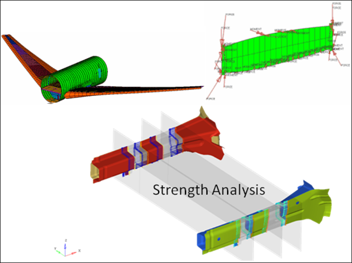
Free Body Diagrams (FBD)
The Free Body Diagram (FBD) tool facilitates the extraction and post-processing of Grid Point Force (GPFORCE) results and can be used create and edit Free Body Diagrams (FBD).

Figure 1.
FBD Utility
The FBD utility extracts grid point force (GPFORCE) data (including forces and moments) for a user-defined element set, and is useful for doing breakout modeling within a sub-modeling scheme. Results can be output for graphical review, a text summary table, and/or a formatted Comma-Separated Values (.csv) file which can be loaded into traditional spreadsheet software packages.- ANSYS: "Element Nodal Force as Vector" and "Element Nodal Moment as Vector"
- Nastran/OptiStruct: "Grid Point Element Forces" and "Grid Point Element Moments"

Figure 2.
- FBD section definition
- Element based sections are defined and modified in this first step of the process. You can define multiple sections, associate elements, associate a node group (optional for resultant summation), or define other attributes (like a summation point, a coordinate system, etc.).
- FBD plot
- Once the sections are defined, you can plot results (Freebody or Resultant Forces/Moments) in this middle step of the process.
- Display controls
- The presentation of the results/plots are controlled in this final step of the process. The various controls allow you to determine how the vectors are drawn in the modeling window, view the results in a summary table, or export/save the results to a .csv or .fbd file.