Implementation
Modeling Requirements
- Weld sections to be analyzed for seam weld fatigue should be meshed with CQUAD4 elements whenever possible. CTRIA3 elements may be used for corner weld if inevitable and for closing the end of weld line if necessary. Other element types are currently not supported for seam weld fatigue.
- The weld should be modeled by a single or double row of CQUAD4 elements. If a 2 sided fillet is to be modeled, a third row of CQUAD4 may be used.
- The thickness of the weld element is the same as the effective throat.
- The mesh size around the weld should be as regular as possible. Although this method is less sensitive to mesh size, a mesh size of about 10 mm would be a good choice according to Fermér, Andréasson, Frodin. This paper showed that large hot spot stress differences did not exist between mesh size 12 mm and mesh size 5 mm in case of a regular mesh.
- The weld element can be referenced through Sets/Parts. Custom Zones assist in creating user-defined sets in HyperLife.
- The weld element normal direction should point outwards such that the normal direction is toward the weld toe, not toward the weld root. The normal direction of weld element plays a critical role in determining the weld toe and the surface to be examined on the base of the weld.
Weld Basics
- Face
- Toes
- Throat
- Root
- Legs

Figure 1. Basic Weld Structure
Good Weld Design Practice
This section provides a basic overview of stress concentrations in welded structures and a few recommendations for good weld design. This section should not be considered as a complete weld design guide and does not cover an exhaustive list of weld design recommendations.
- Weld shape based stress concentration:Figure 2 shows the stress concentration at the toe of a weld. Its magnitude depends on the flank angle, , local weld toe radius, r, and plate thickness, t. The concept of a weld reinforcement is a misnomer as you can see that the stress concentration actually increases with increasing weld metal, that is, an increase in flank angle, .

Figure 2. Stress Concentration vs Weld Radius and Plate Thickness for Seam Weld Fatigue - Weld design based stress concentration:
The second stress concentration comes from the joint design. Stress concentrations arise whenever there is a change in stiffness in the structure. It can result from either an increase of decrease in stiffness. For example, a hole in a plate will have about the same stress concentration as a rigid boss added to the plate. Here are some examples of weld joints contrasting good and poor design practice.
First you need to consider a cover plate welded to a bending beam. A large stress concentration exists at the end of the cover plate because of the large change in stiffness. A better design is shown on the right side where there is a more gradual change in stiffness.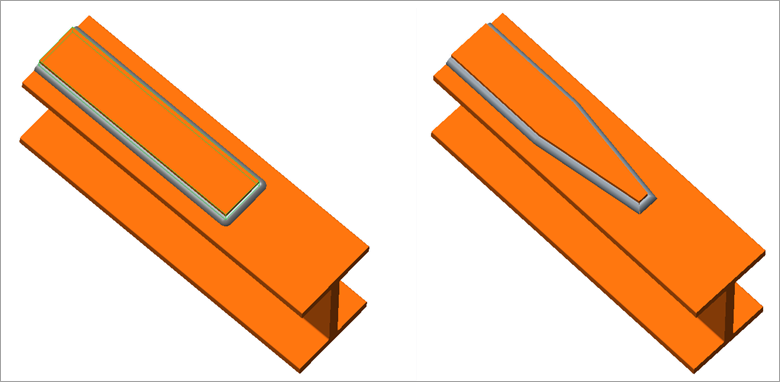
Figure 3. (a) Incorrect Weld Design; (b) Correct Weld Design: Gradual Stiffness GradientA second source of stress concentration is unintentional bending stresses caused by asymmetric geometries. The design on the left will have larger bending stresses than the double lap joint on the right side.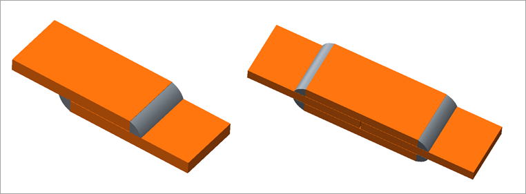
Figure 4. (a) Incorrect Weld Design; (b) Correct Weld Design: Double Lap Joint Symmetric GeometryWelding plates of differing thicknesses or widths is always problematic. Just as above, the easiest geometry to weld has the largest stress concentration. You should always consider moving the welds to lower stress areas in the structure and have a gradual transition in stiffness such as the joint shown Figure 5(b).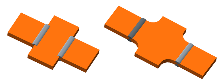
Figure 5. (a) Incorrect Weld Design; (b) Correct Weld Design: Gradual Stiffness Transition