Beams

Use the Beams to create beams and edit their connectivity, properties, and orientations.

Beam entity defines a straight, massless beam of uniform cross section acting between two points (Point 1 and Point 2) that belong to two different bodies (Body 1 and Body 2). The mass of the bean is lumped at Point 1 and Point 2. The stiffness properties for the beam are derived using Timoshenko beam theory.

The beam axis is assumed to be along the x-axis of the Body 2 Reference Marker. The x-axis of the Body 2 Reference Marker is also defined to be the neutral axis of the un-deformed beam. The beam is assumed to undergo small rotational deflections; large rotations are not supported.
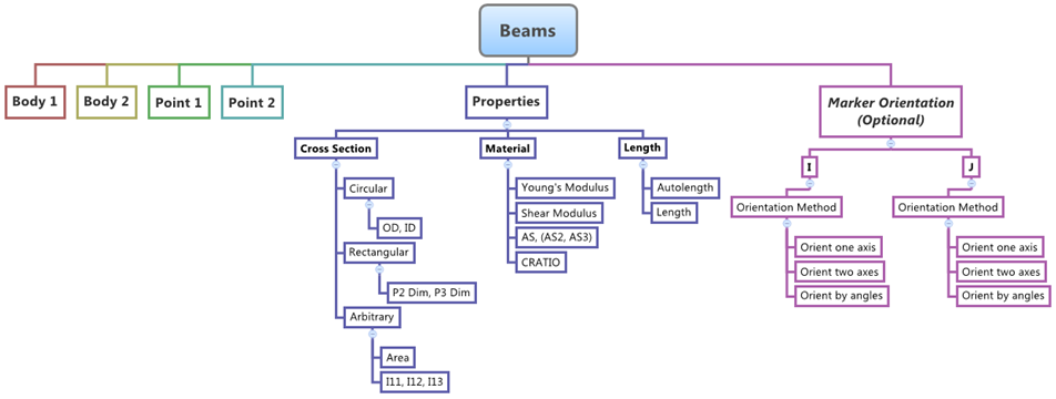
The topological information required to define an Beam is shown in the figure below:


Figure 1.

Create Beams

A beam entity defines a straight, massless beam of uniform cross section acting between two points (Point 1 and Point 2) that belong to two different bodies (Body 1 and Body 2).

The mass of the beam is lumped at Point 1 and Point 2. The stiffness properties for the beam are derived using Timoshenko beam theory. The beam axis is assumed to be along the x-axis of the Body 2 Reference Marker. The x-axis of the Body 2 Reference Marker is also defined to be the neutral axis of the un-deformed beam. The beam is assumed to undergo small rotational deflections; large rotations are not supported.
  1. From the Project Browser, select the system to which the beam entity is to be added.
  2. Right-click on a system in the Project Browser and select Add > Force Entity > Beam from the context menu.
    OR
    Right-click on a beam folder in the Project Browser and select Add Beam from the context menu.
    OR
    Right-click the Beam button on the Force toolbar.
    The Add Beam or BeamPair dialog is displayed.
  3. Specify a label for the beam.
  4. Specify a variable name for the beam.
    By default, variables names of entities in MotionView follow a certain convention. For example, all beam entities have a variable name starting with “bm_”. This is the recommended convention to follow when building models in MotionView since it has many advantages in model editing and model manipulation.
  5. Select whether to create a single beam or a beam pair.
    A beam entity, like most of the entities that are created in MotionView, can be a single entity or a pair entity. Pair entities help in creating models which have symmetric properties.
  6. Click OK to close the window or Apply to continue creating entities.
    Once a beam entity has been added to the model, the panel for the beam will automatically be displayed in the panel area.

Edit Beams

Define the Connectivity of Beams

The Connectivity tab allows you to select the bodies and points to which a beam is attached.

  1. If the Beams panel is not currently displayed, select the desired beams by clicking on it in the Project Browser or in the modeling window.
    The Beams panel is automatically displayed.
  2. Click the Body 1 collector and select the first body to which the beam is attached from the modeling window, or double-click the collector to open the Model Tree (from which the desired body can be selected).
    Note: If the selected beam is a pair entity, first distinguish between the Left and Right tabs in the panel, and then edit the properties. When defining a pair beam, use pair entities for Body 1, Point 1, etc.
    Tip: Check the Symmetric properties option to make the beam properties symmetric. Once this option is activated, MotionView will ask you which side of the values of the pair entity (left or right) is to be used. Selecting any one side will make values of that side as “master” and the values of the other side will gray out and follow the values on the master side.
  3. In the same manner, click the Body 2 collector and select the second body to which the beam is attached.
  4. Click the Point 1 collector and select a point on the first body to which the beam is attached.
  5. Click the Point 2 collector and select a point on the second body to which the beam is attached.

Define the Properties of Beams

The Properties tab allows you to define the properties of a beam with circular, rectangular, or arbitrary cross sections.

  1. Click the Properties tab.
  2. Select a cross section type form the Type drop-down menu.
    If Circular is chosen:
    1. Enter the values for the Young’s Modulus (E) and Shear Modulus (G) in the corresponding fields.
    2. Enter the values of the Outer (OD) and Inner Diameters (ID) of the circular beam. To define a Solid beam, leave the ID value unchanged or 0.0.
    3. Enter the value for the Shear Deflection Correction Factor (AS).
    4. Enter the value for Damping Factor (CRatio).
    If Rectangular is chosen:
    1. Enter the values for the Young’s Modulus (E) and Shear Modulus (G) in the corresponding fields.
    2. Enter the dimensional values of two sides in the fields for P2 Dim: and P3 Dim:. The rectangular cross section will have two perpendicular sides along two axes perpendicular to the axis of the beam.
    3. Enter the value for the Shear Deflection Correction Factor in the directions of the P2 Dim and P3 Dim respectively in the fields AS2: and AS3:.
    4. Enter the value for Damping Factor (CRatio).
    If Arbitrary is chosen:
    1. Enter the values for the Young’s Modulus (E) and Shear Modulus (G) in the corresponding fields.
    2. Enter the value for the Cross Sectional Area in the Area: field.
    3. Enter the value of the Polar Moment of Inertia of the beam cross section in the field for I11:.
    4. Enter the values of the Second Moment of Inertia of the beam along the Y and Z axis of the beam (axes perpendicular to the beam axis) in the fields for I22: and I33:.
    5. Enter the value for the Shear Deflection Correction Factor in the directions of Y axis and Z axis of the beam (axes perpendicular to the beam axis) respectively in the fields AS2: and AS3:.
    6. Enter the value for Damping Factor (CRatio).
  3. Specify the length of the beam by choosing an option from the drop-down menu.
    If Autolength is selected, the length wil be automatically calculated based on the distance between two endpoints. You can manually enter a value for the desired length of the beam by selecting Length. The length option can be used to preload a beam.

Define the I and J Coordinate Systems of Beams

A beam has a coordinate system at each end. The I coordinate system is located at end 1 of the beam and the J coordinate system is located at end 2 of the beam. The I tab and the J tab allow you to orient each coordinate system. By default, the X axis of the J coordinate system points directly at point 1 of the beam.

  1. Click the I tab.
    Note: The default orientation for the beam entity is such that the un-deformed beam axis is oriented along the x-axis of the Body 2 reference marker. The x-axis of the Body 2 reference marker is oriented along the axis defined by the line connecting Point 1 and Point 2 of the beam entity.
  2. Click the Body collector and select the body to which the I coordinate system is attached from the modeling window, or double-click the collector to open the Model Tree (from which the desired body can be selected).
  3. Click the Point collector (under Origin) and select a point from the modeling window or the Model Tree.
  4. Use the orientation options to orient the coordinate system.
  5. Click the J tab and repeat the same steps for the J coordinate system.

Define the Preload of Beams

The Preload tab allows you to define the preload force/torque on the beam entity for MotionSolve.

This tab is not applicable for ADAMS and Abaqus.

  1. Click the Preload tab.
  2. Enter initial force preload values in the X, Y, and Z fields.
  3. Enter initial torque preload values in the Tx, Ty, and Tz fields.
Tip: Beams can be preloaded by offsetting Point 1 from the X axis of the J coordinate system or by making the I and J coordinate systems non-parallel. Beams can also be preloaded by turning off the Autolen option on the Properties tab and directly entering a length for the beam. The beam is compressed or extended appropriately by the solver to satisfy the end positions indicated by Point 1 and Point 2.