Plies
Ply entities define a FEA ply which is the FEA correlation to a physical ply.
- Plies defined by elements
- The shape (area) of an FEA ply is defined by selecting elements which most closely
represent the complex shape of a physical ply. In Figure 1, an
elliptical physical ply shape is defined by the brown line. The corresponding FEA ply
shape is defined by the gray shaded elements of the associated FEA mesh. Typically, if
an element's centroid exists within the bounds of the physical ply shape, that element
is considered part of the FEA ply shape.
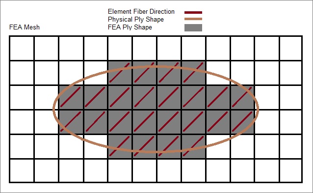
Figure 1. - Plies defined by lines
- Plies can be defined by selecting lines which build a closed area. If CPD data is imported from Catia files, plies are defined on lines.
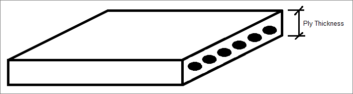
Figure 2.
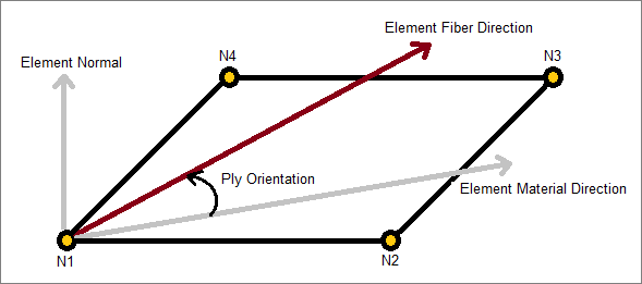
Figure 3.
Once all of the plies which make up a composite structure are defined, just as in the actual hand-layup manufacturing process, plies are stacked in a specific given order within the laminate entity to define a laminate of the structure. It is possible to stack plies, whether they are defined based on geometry or elements.
Turn the display of plies on/off or change the way plies appear in the modeling window with the Ply layers display setting, which can be accessed from the Mesh Display settings on the View Controls toolbar.
Supported Solver Cards
Solver cards supported for plies.
Abaqus Cards
The Abaqus solver has no direct match for a ply, therefore the ply entity does not have a card image in the Abaqus solver interface. Ply entity names will end up in the ply name of the composite properties SHELL SECTION and SHELL GENERAL SECTION, if used in a laminate entity and realized into a zone based model.
Nastran Cards
The Nastran solver has no direct match for a ply, therefore the ply entity does not have a card image in the Nastran solver interface. Ply entity IDs will end up as global ply ID in the PPOMG property card, if used in a laminate entity and realized into a zone based model.
OptiStruct Cards
The OptiStruct PLY card is represented as a ply entity. Plies can be created from the selection of individual elements or from predefined element sets which define the ply shape.
| Card | Description |
|---|---|
| PLY | Defines the properties of a ply used in ply-based composite
definition. Note: Can only be created and edited in the Ply
Editor from the Model Browser.
|
Radioss Cards
The property card /PROP/PLY (TYPE19) and keyword /PLY are represented as a ply entity.
Samcef Cards
The Samcef .PLI card is represented as a ply entity.
Create and Realize Plies
Overview of how to create and realize plies.
Radioss
Create Plies
- In the Model Browser, right-click and select from the context menu.
-
In the Create Ply dialog, define attributes
accordingly.
Option Description Name Ply name. This will define the prop_title attribute of /PROP/TYPE19.
Same as Duplicate an existing ply. Card Image Keyword used for the ply creation. /PROP/PLY if P19_PLY card image is used, or /PLY if PLY card image is used.
Color Color of ply. Dummy ply Create simple ply without a card image. Material Type Type of material assigned to ply. Material Material assigned to ply. This will define the mat_ID attribute in /PROP/TYPE19.
Thickness Ply thickness. This will define the t attribute in /PROP/TYPE19
System Reference system used for the angle calculation of the ply. The system is not linked to an attribute of the /PROP/TYPE19, but can be defined by importing external composite data like FiberSim information. This information will be taken into account during the realization of the ply.
Orientation Fiber angle on the ply. This will define the delta_phi attribute in /PROP/TYPE19.
Integration points Number of integration point through the ply thickness. This will define the Npt_ply attribute in /PROP/TYPE19.
Drape table Drape table to link to the ply. The drape table will not linked to an attribute of the /PROP/TYPE19, but can be defined by importing external composite data like FiberSim information. If specified, a realization of the ply is needed to obtain the initial fiber angle defined with the Radioss cards /INISHE/ORTH_LOC and /INSH3N/ORTH_LOC.
Shape Shape of the ply. The attributes grsh4n_ID and grsh3n_ID of /PROP/TYPE19 are automatically generated.
If the shape is defined by a line or surface, which may be the case when importing CAD/CPD data, a realization of the ply is needed to generate the FE element sets defining the FE shape.
Base Surfaces Base surfaces to be used during ply realization. This is useful when the projection of the shape is not found on a unique surface.
- Click Create.
Realize Plies
Realize plies when ply definitions need to be imported from external composite data, such as FiberSim or CAD/CPD.
During the realization process, the shape of the ply will be projected on the selected FE mesh and, if drape information is available, the corresponding Radioss cards /INISHE/ORTH_LOC, /INSH3N/ORTH_LOC, or /DRAPE will be generated.