Laminates
Laminate entities define laminates, which make up a laminated structure by defining the stacking sequence of ply entities that make up the laminated structure.
- Ply Laminates
- Define laminates which make up flat or slightly curved laminated structures.
- Ply laminates stack ply entities. The stack direction for the plies of a ply laminate
is in the direction of the element's normal.
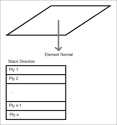
Figure 1.
- Sub-Laminates
- Similar to ply laminates in that they also stack ply entities. However, sub-laminates define only a portion of a laminate rather than a complete laminate structure.
- The stack direction for the plies of a sublaminate is defined by an interface
definition within an associated interface laminate. However, the ply order defined
within a sublaminate must remain in the defined order. An interface definition of an
interface laminate defines which ply of the sublaminate is on “top” and which is on the
“bottom” relative to the elements normal.
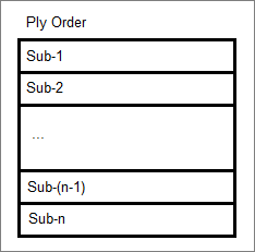
Figure 2. - Interface Laminates
- Define laminates which make up complex laminated structures that wrap around corners.
- Interface laminates stack sublaminates. The stack direction for the sublaminates of an
interface laminate is in the direction of the element's normal. The exact stacking
sequence of the plies of the sublaminates is defined by the interface definitions within
an interface laminate. An interface definition defines which surface plies of two
sublaminates touch, or interface, with each other. Each sublaminate stacked within an
interface laminate must have at least one interface definition.
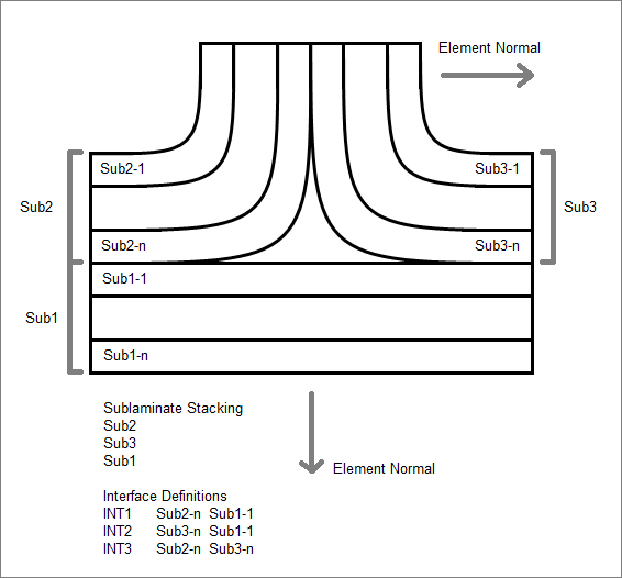
Figure 3.
Supported Solver Cards
Solver cards supported for laminates.
Abaqus Cards
If a laminate is realized, as many composite properties as needed are created to represent the ply and laminate based definition. A ‘template’ composites property (SHELL SECTION or SHELL GENERAL SECTION) has to be assigned all concerned elements first, as the algorithm derives the new properties from the same.
The laminate name ends up in the LAYUP parameter of the Abaqus property.
Nastran Cards
If a laminate is realized, as many composite properties (PCOMPG) as needed are created to represent the ply and laminate based definition. A ‘template’ composites property PCOMPP has to previously be assigned all concerned elements. The PCOMPP property is not exported.
OptiStruct Cards
Laminate realization can be used to convert a ply based model into a zone based model. In this case the export state of all ply related entities (PCOMPP property, PLY and STACK) will be set so that they are not exported.
| Card | Description |
|---|---|
| STACK | Defines the stacking information and stacking sequence for
ply-based composite definition. Note: Bulk Data
Entry
|
Radioss Cards
The stacking definition of the property cards /PROP/STACK (TYPE17), /PROP/TYPE51, and /STACK are represented as a laminate entity.
Samcef Cards
Laminates created will be selected in the definition of the composite properties (.ETASHELL or . ETASOLID).
Create and Realize Laminates
Overview of how to create and realize laminates.
Create Laminates
Radioss
- In the Model Browser, right-click and select from the context menu.
-
In the Create Laminate dialog, define attributes
accordingly.
Option Description Type Defines the type of laminate definition. Name Name of laminate. Save as Duplicate an existing laminate. Card image Card image of the property that will be linked with the laminate (/PROP/TYPE17 > P17_STACK or /PROP/TYPE51 > P51_STACK), or will create /STACK and /PROP/PCOMPP if card image LAM_STACK is used. Color Laminate color. Laminate option Only the Total option is available. Define laminate Select plies, and define the stacking sequence. Phi and Zi will define the attributes of the same name in /PROP/TYE17 or /PROP/TYPE51.
The stacking sequence can be modified at any time using the Entity Editor.
You can modify the stacking sequence of a set of defined plies at any time by right-clicking on the laminate in the Model Browser and selecting Edit from the context menu.
- Click Create.
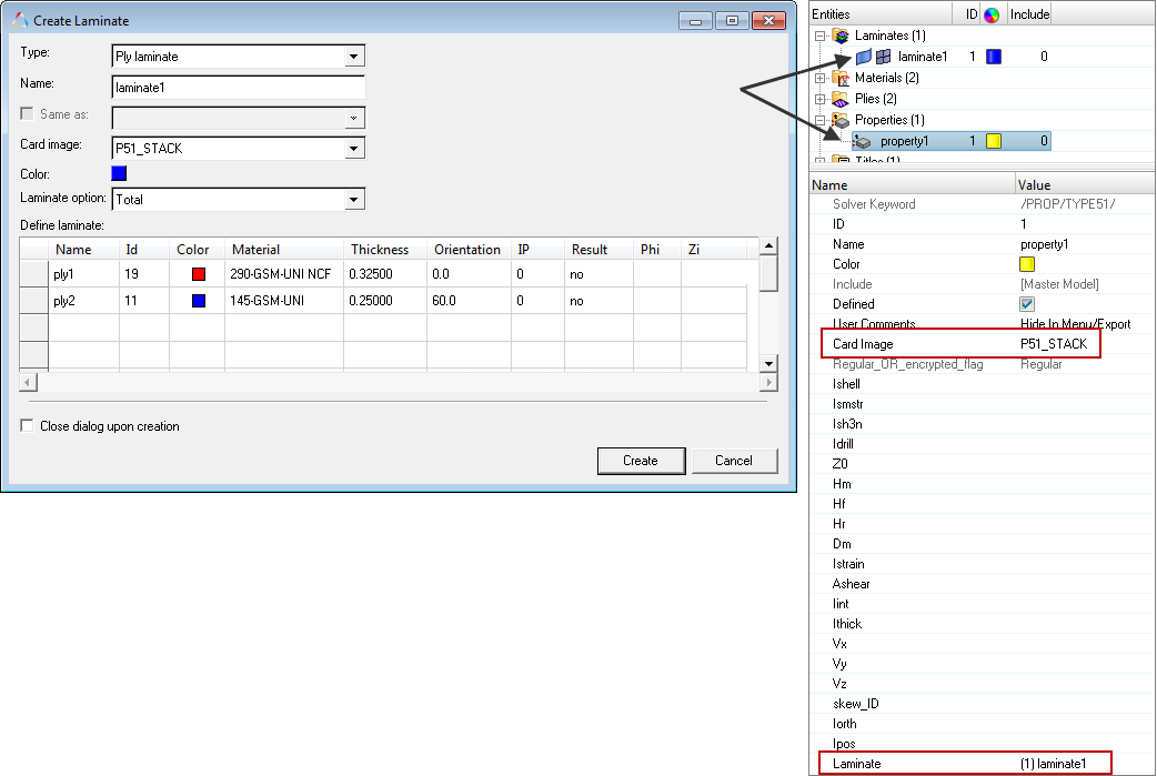
Figure 4.
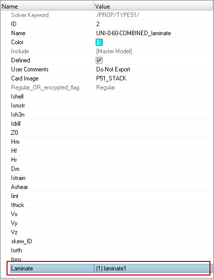
Figure 5.
Realize Laminates
A ply based model is converted into a zone based model. The realization algorithm creates as many properties as needed (as a copy from the template property) to represent the ply/laminate definition. Each region of the model with a unique set of layers will get its own property.