Fatigue Input/Output
Fatigue input for Spot Weld Fatigue Analysis can be divided into the following categories:
Fatigue Element Identification
- The spot welds (CBAR, CWELD, CBEAM) are referenced with the connected sheets as groups. These groups are currently referenced through components.
- The spot weld diameter, which is a function of the minimum shell element thickness, should be input in the Assign Material dialog.
- The result file should contain the shell thickness output to be automatically referred to the HyperLife Assign Material tool.
- CHEXA elements
can be used to define the weld element for Spot
Weld Fatigue Analysis. In such cases, the grid
point forces are resolved into corresponding
forces and moments at the face centers of the
opposing faces connected to the shells. The faces
of the CHEXA element attached
to the sheets should always consist of grid points
in the following order.

Figure 1. Faces of the CHEXA that Should be Used as Connection Faces with Shells for Spot Weld Fatigue
Additionally, the default weld element diameter of the CHEXA element for spot weld fatigue is equal to two times the smallest distance from the attachment face centroid to the edges.
Fatigue Parameters (Spot Weld Fatigue Dialog)
Figure 2.
- The RUPP method is currently applied to calculate the spot weld fatigue analysis.
- The spot weld fatigue parameters are applied in this dialog.
- Mean stress and thickness corrections
are to be activated if the corresponding
parameters are to be applied in the Assign
Material dialog.
For more information on FKM mean stress correction, see the FKM section under Uniaxial S-N Fatigue.
- FE Model units are specified in this
dialog. The default unit specified is MPa.
Thickness reference will be automatically modified
based in the FE model unit selection.

Figure 3.
Fatigue Material
- The material properties (SN curve attributes for sheet 1, sheet 2, and the nugget) to be associated with the spot weld group are specified in the Assign Material dialog (SN attributes from the My Material or Material Database tab).
- The mean stress sensitivity value and the thickness correction values are specified in the Assign Material dialog.
- By default, the shell thickness of the sheets is referenced from the model. The sheets are editable in HyperLife.
- The spot weld diameter is to be specified in the Thick/Dia entry in the Assign Material dialog.
- TREF is set to 25mm by default, which is
equivalent to 1 inch, as specified by the
standard.
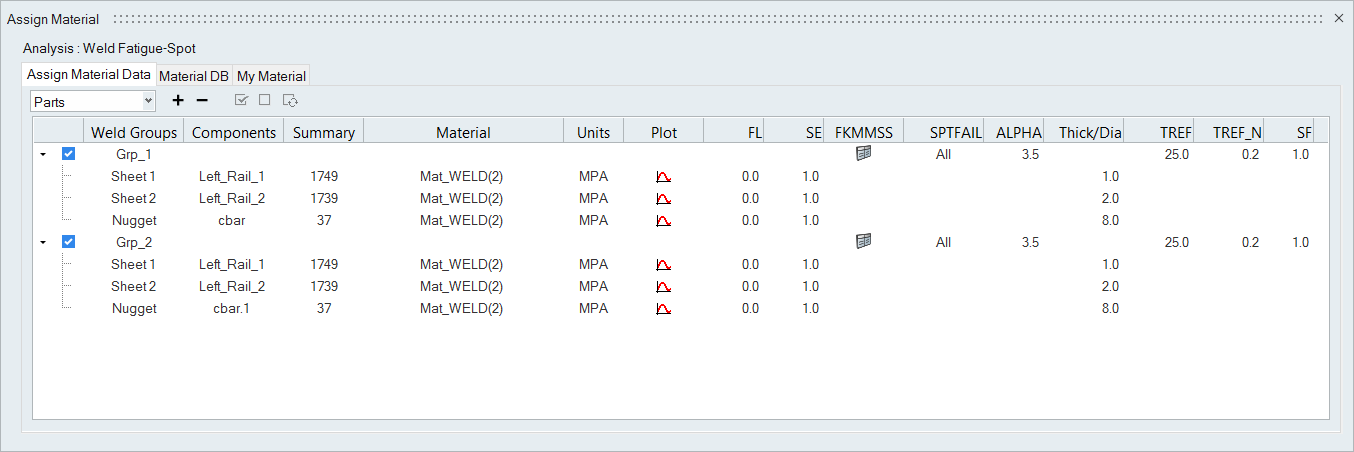 Figure 4.
Fatigue Loads
- Similar to regular fatigue analysis, the fatigue loads are specified in the Load Map tool.
Output
Output for Spot Weld Fatigue Analysis is provided similar to regular Fatigue Analysis results. Damage and Life results for the SHEET, NUGGET, ALL or Auto are available based on the SPTFAIL selection in the Assign Material dialog. The damage calculation lists the worst damage if Auto is selected.