Create and Edit Feature Edges
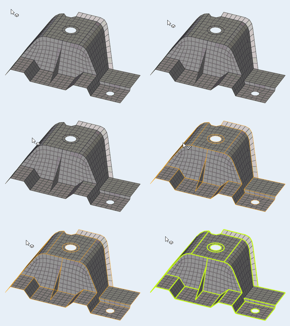
Use the Feature Edges tool to create and edit mesh controls on an edge.
Create Feature Edges

Figure 2.
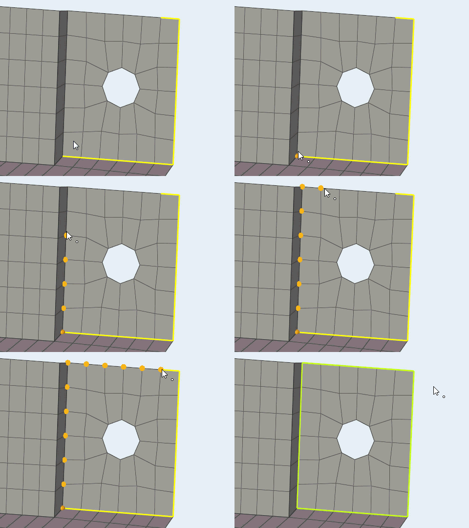
Edit Feature Edges

Figure 4.
- Click Review on the guide bar
to review defined node paths. Click
 and
and  to cycle through options
and
  to exit review mode.
 - Click
 on the guide bar to delete all feature edges.
Feature Edges Options
Create
- Feature angle
- The maximum angle allowed between the normals of two connected shell elements. When an angle exceeds this value, a plot element is created.
- Method
- The method to use for calculating features.
- Ignore normals
- Ignore the normal directions of the elements when creating features.
- Merge small areas
- Combine small areas; for example, a long but narrow strip that might result in two parallel feature lines very close to one another would instead create only one feature line.
- Create
- Choose between creating plot elements or lines.
- Break angle
- The angle above which a line will be split into two lines.
- Smooth
- Creates curved (smooth) lines rather than straight segments.
Edit
- Auto select during preview
- Show preview by joining two ends of open loop.
Keyboard Shortcuts & Mouse Controls
| To do this | Press |
|---|---|
| Append components/elements | Ctrl + Left Mouse Click |
| Deselect components/elements/nodes | Shift + Left Mouse Click |
| Cycle between component and element selection Create tool |
Tab |
| Exit tool | Esc |

 to define feature
options.