Manage Representations
About Representations
The CAD representation forms the basis of the Common representation, which in turn is the basis of all subsequent discipline specific mesh representations. A part can contain multiple representations.
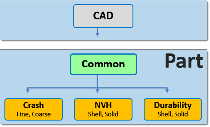
Figure 1. Hierarchical Relationship of Representations
A folder based Representation repository stores all CAE data that is required during the model build and assembly process. CAE data stored in the Representation repository includes the geometric and FE representation of the parts that comprise the subsystem specific model hierarchy.
You can import a BOM via a neutral file format such as PLMXML or manually create a part structure using the Part Browser context menu.
Common Representation
The Common representation is derived from the CAD representation and forms the basis of all subsequent discipline specific mesh representations.
For sheet metal parts, the Common representation consists of midsurfaced geometry or FE. The CAD is sent to the Batchmesher for midsurface extraction; upon completion it is saved into the repository and you can elect to immediately import the representation into the session.
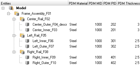
HyperMesh entities are generated from the PDM metadata, if available, in the post-run procedure of the BatchMesh operation. The PDM PID is assigned to the component and property, the PDM MID and PDM material is assigned to the material and the PDM Thickness is assigned to the Thickness attribute of the property. If the PDM Thickness is blank, the CAD Thickness calculated during the midsurface operation is automatically assigned to the Thickness attribute of the property.
For parts such as castings and tailor-welded blanks, you can save CAD representations as Common models.
Alternatively, you can send solid parts to the Batchmesher. If thin-solid detection is enabled in the Common representation parameter file, then solids will be detected and saved as the Common representation without processing. By default, the midsurface algorithm skin is used. CAD representation does not need to be loaded into the session in order to generate the Common representation since it is sent directly to the Batchmesher for processing.
When you select a discipline specific mesh representation from the Change Representation dialog, Create tab, the Common representation residing in the repository is automatically sent to the Batchmesher for processing. If the Common representation does not exist it will be automatically generated.
Discipline Specific Mesh Representations
Create Representations
Representations utilize the mesh parameter and criteria files that are included with HyperMesh. You can find these files in the Batchmesher. The Param File and Criteria File fields display the representation specific mesh parameter and criteria file.
Common representations form the basis of all subsequent discipline specific mesh representations. When you select a discipline specific mesh representation from the Change Representation dialog, Create tab, the Common representation residing in the repository is automatically sent to the Batchmesher for processing. If the Common representation does not exist it will be automatically generated.
-
In the Change Representation dialog, Create tab, select
a desired representation.
The availability of the selected representation in the repository is displayed next to the representation type within parentheses.
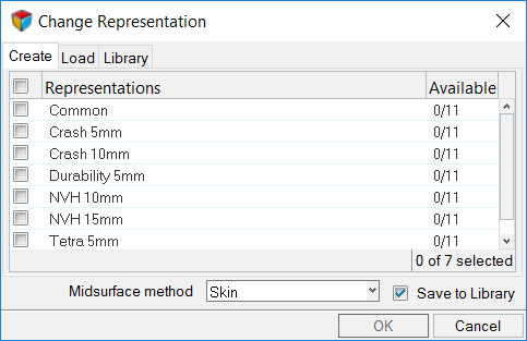
Figure 3. Available Representations. (0/11) common representations available in the repository. -
Click OK.
All representations are sent to the Batchmesher for processing in parallel. Upon completion, all representations are automatically saved to the repository.
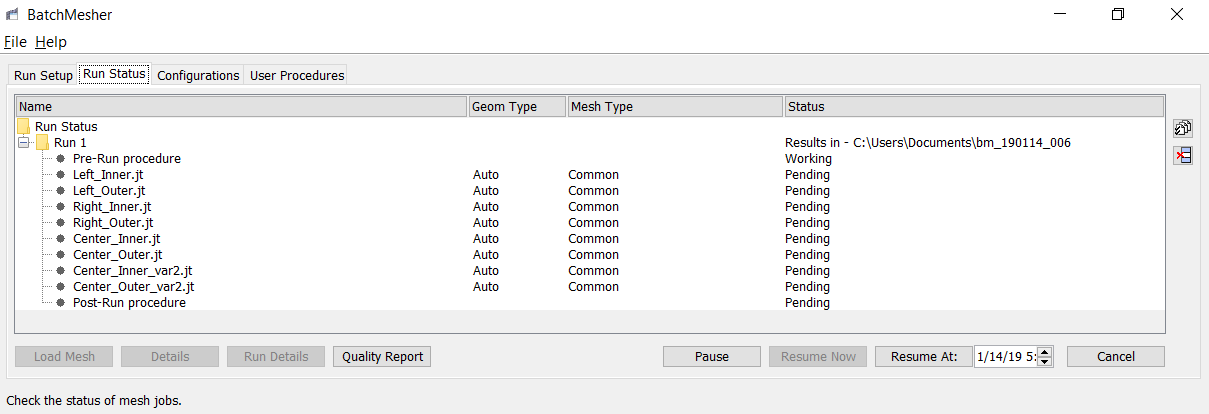
Figure 4. BatchMesher Processing
Define Representations
Create your own user defined representation. User defined representations are saved to the settings and will be available in subsequent HyperMesh sessions.
- In the Part Browser, right-click on part assemblies or parts and select from the context menu.
- In the User Representation dialog, click + to add a new representation.
- In the Representation field, enter a name for the representation.
- In the Param File and Criteria File fields, select the appropriate mesh parameter and criteria file.
- If the representation is for solids, select the Solid checkbox.
- Click OK.
Add Representations
Part representations can be added from external sources such as solver decks and HyperMesh binary files or from the Part Library.
Add Representations from External Sources
Add representations from external sources for a single part or for multiple parts and part assemblies.
When selecting a part assembly or multiple parts, the Add Representations dialog enables you to map and associate representation files to multiple parts simultaneously.
If appropriate metadata is available in the BOM, then the alias values will be preselected. After choosing a Representation Folder, representation files will be mapped according to the HyperMesh naming convention. You can then manually select or update any of the alias and representation file values.
- Skip.
- Any Part which does not have a mapped or selected representation.
- OK.
- Alias and representation are chosen for the part.
- Overwrite.
- Part already has a representation which will be overwritten by the selected mapping.
- Duplicated.
- The same representation file is chosen for more than one part, or the chosen representation file is already used by another part in the same BOM. You cannot click OK to add the representations when representations are duplicated.
- In the Part Browser, right-click on the part assemblies or part(s) and select the context menu.
-
In the Add Representation(s) dialog, define options
accordingly.
To add representations for Do this Single part - From the Representation field, specify a desired representation
type to which a representation file will be added.
- Choose a default representation type.
- Enter your own user defined representation into the field.
- If you entered your own representation, select the appropriate mesh parameter and criteria files.
User defined representations with defined mesh parameter and criteria files created in the Add Representation dialog will be available in the Change Representation dialog, Create tab. User defined representations with undefined mesh parameter and criteria files created in the Add Representation dialog will not be available in the Change Representation dialog, Create tab, but will appear in the Load tab if a representation is found in the repository.
The availability of the selected representation in the repository is displayed next to the representation type within parentheses.
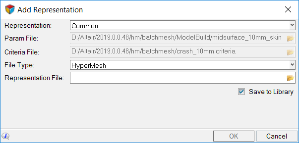
Figure 5.Multiple part or part assemblies - In the Representation Folder field, navigate to the representation file.
- Select the parts to map and associate with the representation file.Note:
- You cannot add CAD or connectors.
- You can select Part or Part Assembly for adding the representation.
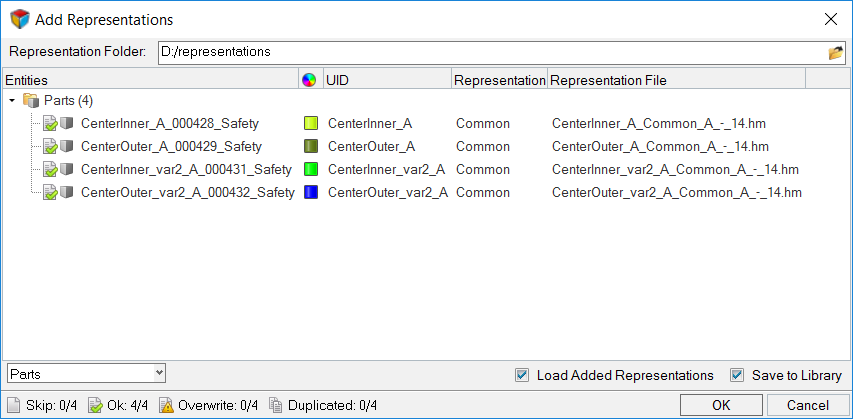
Figure 6. - From the Representation field, specify a desired representation
type to which a representation file will be added.
- To save the representations to the Part Library select the Save to Library checkbox.
- Click OK.
Add Representations from the Part Library
-
Click OK.
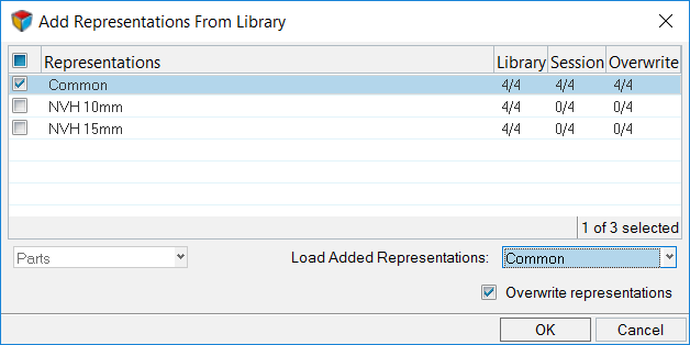
Figure 7.
Add Representations to the Part Library
After importing a BOM, you can add CAD representations to the Part Library.
- In the Part Browser, right-click on a part/part assembly and select from the context menu.
- In the Add Representation to Library dialog, select representations and click OK.
The Add Representation to Library dialog displays information regarding the availability of representations in library, session, and overwrite details.
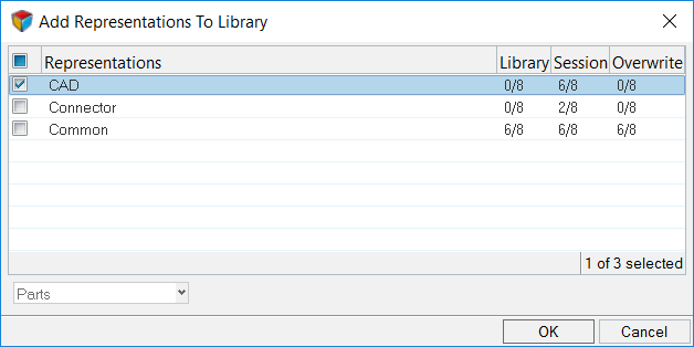
Figure 8.
Browse Library Content
Review library content using the Library Viewer.
-
Select the Part that contains the representations you would like to
review.
A list of properties associated with the Part are displayed in the Properties pane.
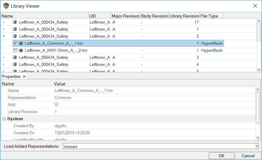
Figure 9. Library Viewer
Load Representations
Part representations can be loaded from your current HyperMesh session or from the Part Library.
Load Representations from Current HyperMesh Session
-
In the Change Representation dialog, Load tab, select a
type of representation to load.
Representations that exist in the repository are shown in the Representations column, and their availability is indicated in the Available column.
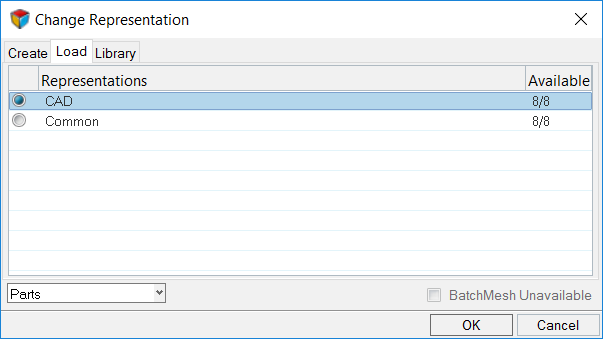
Figure 10.
Load Representations from the Part Library
After importing a BOM that has representations saved in the Part library, you can load the saved representations.
- In the Part Browser, right-click on a part/part assembly and select from the context menu.
- In the Change Representation dialog, Library tab, select representations and click OK.
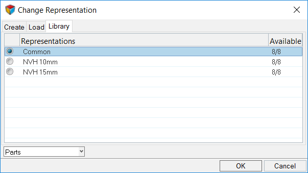
Figure 11.
Reload Representations
Restore part representations to their original state.
Unload Representations
Unload part representations from a session.
- In the Part Browser, right-click on the model, part assemblies, or parts and select from the context menu.
- In the Confirm Unload Representation dialog, click Yes to unload the selected representations.
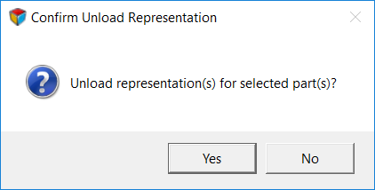
Figure 12.
Update Metadata From PDM
Sync Metadata To PDM
Sync PDM metadata (PDM PID, PDM Thickness, PDM Material, and PDM MID) based on a selected part or part's metadata (PID, Thickness, Material, MID).
Save Representations
After importing a BOM and creating respective representations, you can save the representations locally or in the Part Library.
Parts without a UID cannot be saved to the Library. Considering this, the UID field in the Save Representation dialog is user editable.
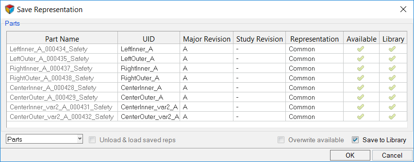
Figure 13.
Delete Representations
Part representations can be deleted from the current HyperMesh session and from the Part Library.
Delete Representations from the Current HyperMesh Session
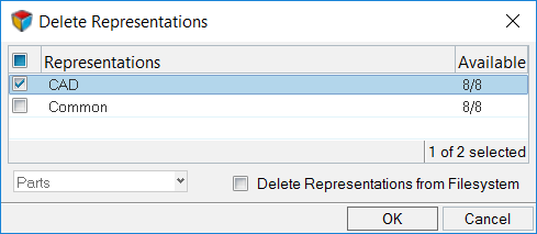
Figure 14.
Delete Representations from the Part Library
- In the Part Browser, right-click on part assemblies or parts and select from the context menu.
- In the Delete Representations From Library dialog, select representations to be deleted.
- Click OK.
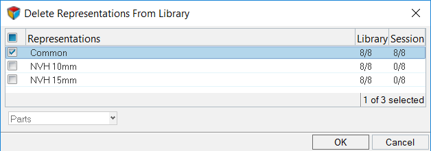
Figure 15.
Representation Load Settings
Settings to configure the representation entity management behavior.
Open the Representation Load Settings dialog by right-clicking in the Part Browser and selecting .
The representation entity management settings work independent of the import binary and import deck entity management settings.
- Offset ID.
- Merges incoming attributes with conflicting IDs into the session, and offsets their IDs.
- Keep Existing Attributes.
- Maintains existing in-session entity attributes and incoming conflicting entity IDs.
- Keep Incoming Attributes (default).
- Maps incoming entity attributes to the in-session entities.
When Offset ID is selected for components, both incoming and existing geometry and FE residing in the component with conflicting IDs are kept. When Keeping Existing Attributes or Keep Incoming Attributes are selected for components, incoming geometry and FE that resides in the component with conflicting IDs are kept.