Generate Midmesh
Automatically generate a mesh at the midplane location, directly from the input geometry (components, elements, solids or surfaces), without first creating a midsurface.
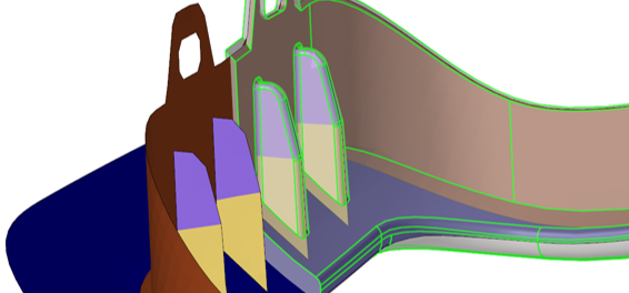
Figure 1. Midmesh Result Example
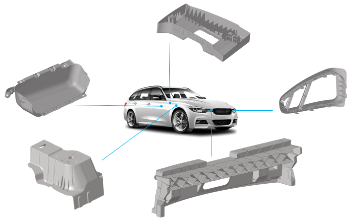
Figure 2. Direct Midmesh Supported Parts
The resulting output consists of 2D shell elements created with the user-provided target size, as well as 1D elements defining the topology of the mesh (vertices/edges/faces). Midmesh generation is also multithreaded to take advantage of multi-core environments.
Midmesh Generation Workflow
There are several steps involved in generating a good quality midmesh. Following the workflow shown in Figure 3 helps guarantee the best result with minimal manual effort.
- Nominal Run
- Extract the base midmesh.
- Cleanup Resulting Topology
- Use the semi-automated midmesh edit edge and edit face tools to correct the 1D topology and fix any bad/missing faces. The goal is to prepare the model for final remeshing.
- Rebuild Mesh
- Remesh to the final size and quality using the rebuild mesh functionality, and correct any remaining mesh quality issues.
- Apply Thickness
- Map the thickness from the original solid to the midmesh via the Map Thickness tool.
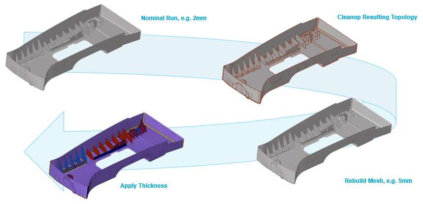
Figure 3. Midmesh Workflow
Create Midmesh
Midmesh generation is possible on dirty geometry, but a cleaner output can be obtained by removing duplicate or overlappinng surfaces, stitching free edges, removing logos and other small features that are not of interest, and merging any solids that should be topologically connected.
It is recommended to use a smaller extraction size (for example, 2 or 4mm depending on model scale) in order to get a good sampling of the input geometry. The final rebuild mesh step takes care of remeshing to the desired size and quality. Using an extraction size smaller than the representative feature size will not necessarily give better results and will take significantly more run time.
- From the 2D page, click the Midmesh panel.
- Select the create subpanel.
-
Define options accordingly to control the resulting midmesh output.
Option Action ignore flat edges Do not imprint flat edges from the input geometry to the midmesh. 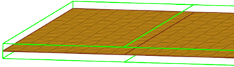
Figure 4. Option Disabled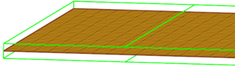
Figure 5. Option Enabledflatten connections Align/flatten the midmesh at ribs/connections. 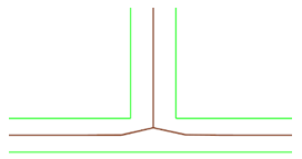
Figure 6. Option Disabled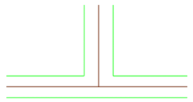
Figure 7. Option Enabledsuppress proximity edges factor Remove 1D topology edges within the given factor of the minimum size from the criteria file. 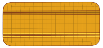
Figure 8. Option Disabled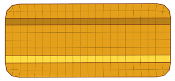
Figure 9. Option Enabledcombine non-manifold edges factor Join non-manifold edges within the given factor of the minimum size from the criteria file. 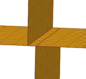
Figure 10. Option Disabled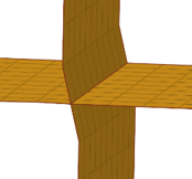
Figure 11. Option Enableddefeature openings with width < Remove small holes and openings less than the specified width. 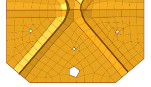
Figure 12. Option Disabled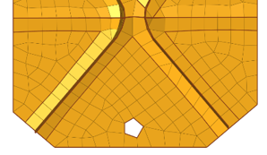
Figure 13. Option Enabled - Optional:
Edit the min size and target element
size settings in the criteria file to control the resulting
midmesh output by clicking edit criteria.
Option Action Target element size Target element size for the finalized mesh. This can be different from extraction size. It is used for internal calculations for the output mesh to be ready for rebuilding with the same criteria. Min size Minimum size allowed in the finalized mesh. This in combination with the ‘suppress proximity edges factor’ and 'combine non-manifold edges factor’ can ensure that the output mesh is ready for rebuild with the same criteria. - Click create.
Edit Midmesh
Once the midmesh is generated, there may be problem areas that need to be corrected. The 1D topology is important for the rebuild mesh operation, and care must be taken to prepare it accordingly. In addition, making sure the faces do not have intersected, overlapped, or missing elements, and that they have proper alignment, is also essential. Specialized midmesh edit tools streamline the process of repairing the 1D topology edges, and correcting issues with the midmesh faces.
-
Select the edit edge subpanel access tools which can be
used to repair 1D topology edges.
Option Action create mid-edge Create a new mid-edge, using the input geometry as a guide. 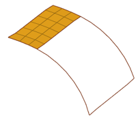
Figure 14. Before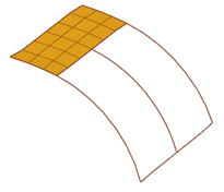
Figure 15. Aftersplit by two nodes Create a new edge between two nodes. 
Figure 16. Before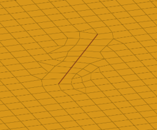
Figure 17. Aftersplit by node-edge Create a new edge between a node and an edge, using a shortest, tangential or mixed path. 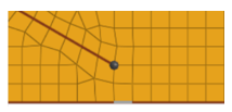
Figure 18. Before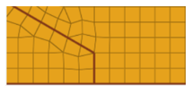
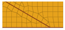
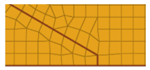
Figure 19. Afterdelete edge Delete an edge. 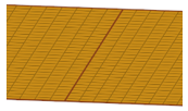
Figure 20. Before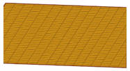
Figure 21. Aftert-edge align Align/flatten a t-connection edge to a surface. 
Figure 22. Before
Figure 23. Afterby geom edge align Align mesh edges to input geometry lines, and smooth the mesh, or imprint new geometry edges onto the midmesh. 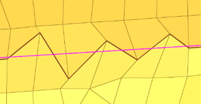
Figure 24. Before Align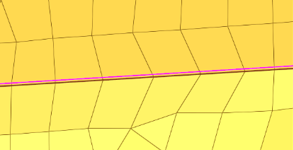
Figure 25. After Align -
Select the edit face subpanel to access tools which can
be used to correct issues with midmesh faces.
Option Action fill face Create a mesh within a closed 1D topology loop, attempting to keep tangency. 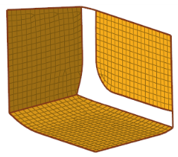
Figure 26. Before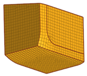
Figure 27. Afterrepair face Attempt to fix topological problems (holes/gaps/cracks, intersections, slivers, overlaps) in the mesh and remesh the face. 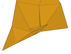
Figure 28. Before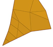
Figure 29. Afterdetect intersections/gaps Detect intersecting element clusters and holes/gaps/cracks, and create element sets for further handling. 
Figure 30. Before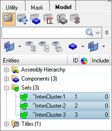
Figure 31. Afteralign face Align a selection of elements to an input geometry face, with optional offset. 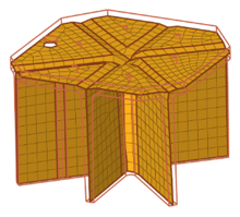
Figure 32. Before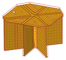
Figure 33. After
Batchmesher Midmesh Generation Rules
Midmesh generation is also supported from within Batchmesher.
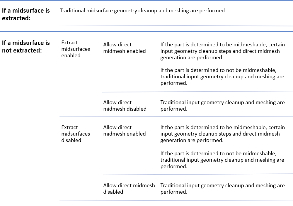
Figure 34.