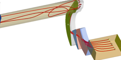
| 1. | From the Streamlines panel, click Add. |
Rake 1 is added to the list.
| 2. | From the Rake type drop-down menu, select Line. |
| 3. | Define the end points of the rake: |
Pick two nodes on the model.
Or
|

|
Use the node/vector entity selector (N1, N2) and the Select by ID dialog to select your desired nodes.
Altair HyperView will automatically provide the X, Y, Z positions (coordinates) of the nodes at the time of definition.
Or
If you know the specific coordinates of the end points defining the rake, you can simply enter them in the X, Y, Z coordinate text boxes.
| Note: | It is important to make sure at least a portion of the rake (at least one of the rake headers) is in the fluid field. Therefore it is highly recommended that once the nodes have been selected, that you then modify the point coordinates by giving them a small offset to make sure the rake is in the "main stream", instead of the boundary layer. This will ensure that full streamlines are created. |
You can also use the graphical manipulator to modify the rake location to ensure it is in the “main stream” and that all requested streamlines are generated.
|
| 4. | Select the integration mode for the rake (Downstream, Upstream, or Both) from the Integration mode drop-down menu. |
| 5. | Enter the number of desired seeds in the Number of seeds text box. |
| 6. | From the Source drop-down menu, select the vector field to be used for streamline creation (typically the velocity field). |
| Note: | You can also click Advanced Options to open the dialog which allows you to change a number of parameters that control how the streamlines are generated. |
|
| 7. | Enter/select your desired display options: |
| - | Auto-generate streamlines - activate the check box to automatically generate streamlines upon release of the mouse button. |
| - | Draw as tube - active this option to draw the streamlines as tubes instead of lines. |
| - | Auto-color streamlines - activate the check box to use the number specified in the Number of colors text box to distinguish streamlines. |
| - | Number of colors - enter the number of distinct colors to use when the Color streamlines option is activated (1-14). |
| - | Streamline size - enter the relative scale for the streamline thickness (the value must be a positive whole number). |
| - | Seed marker size - enter the size of the seed nodes which are being used as the starting point for the streamline generation. |
| 8. | Click Create Streamlines to create and view the streamlines. |
See Also:
Streamlines


