MV-7010: Co-Simulation with Activate - Quadrotor Control
In this tutorial, you will learn how to use MotionSolve and Activate in a co-simulation to control a Quadrotor model.
Activate is a software solution for multi-disciplinary, dynamic system modeling and simulation. The software is especially useful for signal-processing and controller design that requires both continuous-time and discrete-time components.
A co-simulation enables MotionSolve and Activate models to communicate with each other during simulation. An ideal use case for co-simulation is the development of a control system for a multibody dynamics model.
Quadrotor Model and Control
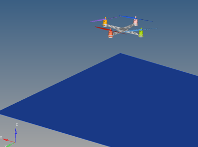
A quadrotor model is a multirotor helicopter that uses 2 sets of identical fixed pitched propellers (2 clockwise and 2 counter-clockwise) to control lift and torque.
Control of vehicle motion is achieved by altering the rotation rate of one or more rotor discs, thereby changing its torque load and thrust or lift characteristics.
In MotionView you will create the quadrotor frame with 4 superblades and add the rotors motions. A set of forces will be used to represent the wind disturbance.
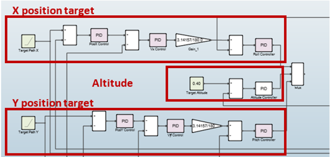
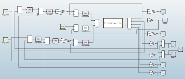
Activate, through co-simulation with MotionSolve, will implement a controller to impose altitude and direction in quadrotor trying to compensate against the wind effect.
Exercise
Copy the Quadrotor_start.mdl, rotor.h3d, shaft.h3d, superblade.h3d and Quadrotor_Control_Start.scm from <installation_directory>tutorials\mv_hv_hg\mbd_modeling\motionsolve\cosimulation\activate> to your <working directory>.
Reviewing the Model
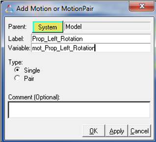
Specifying the Propellers Motions
Specifying the Velocity of the Propellers
-
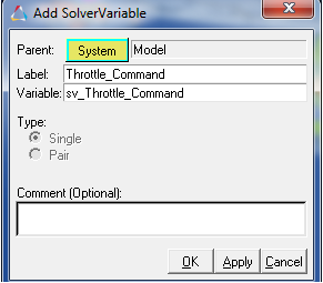
Before you can specify the velocity, you must first create the solver
variables.
-
Now you can update the propeller motion velocity.
Adding Wind Disturbance Forces
To represent the wind effect and thrust of the quadrotor, a set of forces and moments must be defined.
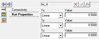
The wind disturbance is represented as a combination of torques in the X and Y axle applied at the vehicle center.
Where,
= Thrust force
= Thrust factor (Defined considering the propeller geometry, air density,m and spin area. For this analysis Tf= 2.1998e-5).
= Propeller Angular velocity
-
Create the wind disturbance force.
-
Create the thrust force.
- To save your model, click Save As and save it with the name Quadrotor_tutorial.mdl
Creating Control Inputs and Plant Outputs
To modify the MBS model to work in a Co-Simulation Mode you need to add solver arrays and solver variables entities in MotionView model. The solver variables contain the individual plant input and output values. The solver arrays define the plant input and output to communicate with Activate.
-
Adding solver variables.
- The individual plant input solver variables were already defined with the propellers motion in Specifying the Velocity of the Propellers. They are Throttle_Command, Roll_Command and Pitch_Command.
-
Next, you will define the individual plant output values, which are Altitude,
Roll Angle, Pitch Angle, X position, Y position, X velocity and Y
velocity.
-
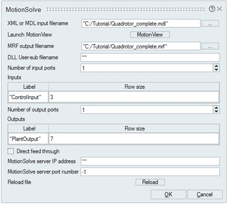
Create two solver arrays, ControlInput and PlantOutput, to communicate with
Activate.
- Save your model.
