Nastran Interface
Overview of the Nastran interface.
- Two sub-profiles are available for the Nastran interface:
- MSC Nastran
- NX Nastran
- During input, the Nastran interface assumes that the continuation line always follows the line before, therefore no continuation cards are needed in the input file. During export, HyperWorks X writes "+" or "*" as a continuation card to ensure that the continuation line follows the reference card.
- Warnings and error messages are written to an open text file for your review. You can save this file. All the lines in the input file that are unrecognized by the translator are written to unsupported cards, which can be edited.
- The Nastran input translator supports single, double, free, and fixed formats.
- Two templates are available for export and viewing (editing) Nastran cards. The Nastran/general template outputs all cards in a single precision, fixed format. The nastran/generallf template outputs System, Grid, Element, Load, Subcase, Property, and Material cards in a fixed, double precision (Long) format.
- By selecting the Nastran user profile, you can work with pre-defined panels that are more specific to Nastran usage.
- Symbolic substitution is supported as parameters in the MSC Nastran user profile for properties and materials. All the attributes in materials and properties can be parameterized.
- Before exporting or editing Nastran cards, a Nastran template must be loaded. Setting the user profile to Nastran automatically loads the Nastran template.
- HyperWorks X reads and writes certain HyperWorks X commands in the Nastran bulk data file as comments. These comment cards enable HyperWorks X to preserve pre-defined preferences across sessions. It is strongly suggested that you do not hand edit these cards.
Thermal Surface Elements for Nastran
HyperWorks X supports the modeling of boundary condition surface elements used in heat transfer solution sequences in Nastran (such as SOL400).
| Thermal Surface Element | Import | Export | Edit | Create |
|---|---|---|---|---|
| CHBDYE | Y | Y | Y | Y |
| CHBDYG | Y | Y | Y | N |
These cards are represented as slave elements as part of a CONDUCTION, CONVECTION, or RADIATION group in HyperWorks X, and are created through the Interfaces panel.
Convection
- Group type = CONVECTION
- Group Card Image = PCONV
- Slave element type = CHBDYE/CHBDYG
- Additional associated cards = CONV: Represented as a checkbox inside slave element card preview.
Radiation
- Group type = RADIATION
- Group Card Image = RADM
- Slave element type = CHBDYE/CHBDYG
- Additional associated cards = VIEW: Represented as a loadcollector in HyperWorks X
CHBDYE Side Conventions for 3D Elements
To automatically calculate the appropriate value of the SIDE parameter for newly created CHBDYE slaves on solid elements according to the specified face nodes and break angle, go to the Interfaces panel, Add subpanel, and set the slave option to face.
CHBDYE Side Conventions for 2D Elements
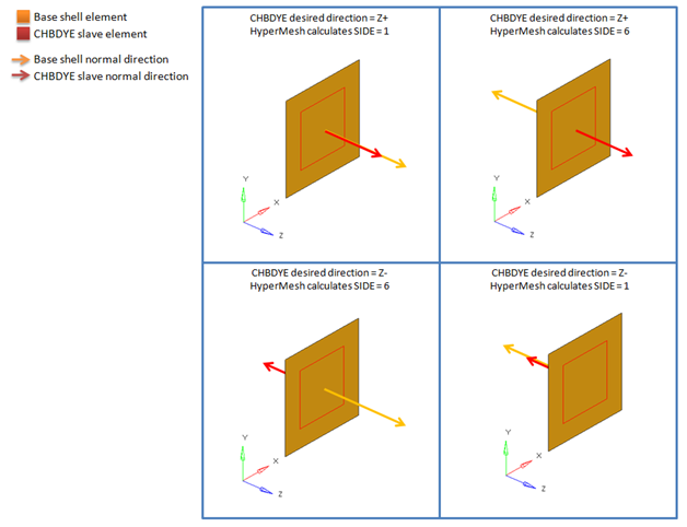
For CHBDYE slaves on 2D shell elements, HyperWorks X will automatically assign a SIDE parameter value of 1 (top) or 6 (bottom), depending on CHBDYE normal direction. Use the Normals panel inside the Tool menu page to change CHBDYE normal direction.

Figure 1. Resulting SIDE Value for CHBDYE Slave on 2D Shell Element
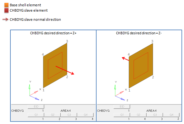
CHBDYG Side Conventions for 2D Elements

Figure 2. Resulting Node Order for CHBDYG Slave on 2D Shell Element