|
»Click here to display Table of Contents«
|

Contact |

|

|

|

|
|
Contact |
|
|
|

|
|
»Click here to display Table of Contents«
|
Contact |
|
|
|
|
|
Contact |
|
|
|
|
| Note: | To accept selection(s), press ENTER, click Yes or right-click the mouse button; or select Cancel. |
| Note: | It is strongly recommended to remove the intersections before removing the penetrations. |
| 1. | Select parts in the tree (see Selection List for information on how to select parts in the tree). |
| 2. | From the menu bar, select Quality > Check Intersections of Tree Selection. |
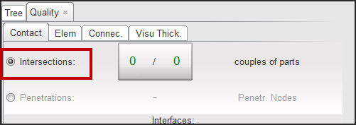
The Contact sub-window appears.
| 3. | Click the Intersections radio button to activate it. |
| Note: | It is easier to see the intersections if the model is in Poly. + Line view (from the Display menu). |
The nodes of the fixed parts will not move during the disintersection process.
| 1. | Click |
| 2. | Click |
| 3. | Answer the question in the pop-up dialog window. |
| 4. | Click |
| 1. | Select the entire intersection by clicking |
| 2. | Click |
HyperCrash starts the automatic disintersection. The following window appears:
| 3. | Click Interrupt to stop the disintersection process. |
Some intersections cannot be removed automatically and need to be removed manually or semi-automatically.
| 4. | From the intersection list, select the first one. |
| 5. | Click |
If the intersection can be removed automatically, it disappears from the list.
If HyperCrash displays some node displacement proposals with blue arrows:
| • | Check if the proposals are correct. |
| • | If yes, click |
| • | If the proposals are not correct, click |
| • | Click |
| • | Click |
If nothing happens, it means HyperCrash cannot remove the intersection automatically. Some buttons are available to move the nodes manually using the mouse.
| 1. | Move the nodes one-by-one (Move nodes 1 by 1): |
Button |
Behavior |
|
move the node in the plane defined by the neighboring elements. |
|
move the node in the plane defined by the node to move and two other nodes. |
|
move the node along the normal of a plane defined by three nodes (the node to move and two other nodes). |
|
move the node in the screen plane. |
(See Move node using the mouse for further explanation.)
| 2. | Move several nodes at the same time (Move nodes Multi): |
Button |
Behavior |
|
move several nodes in the plane defined by the neighboring elements of the last selected node. |
|
move several nodes in the plane defined by the first selected node to move and two other nodes. |
|
move several nodes along the normal of a plane defined by three nodes (the first node to move and two other nodes). |
|
move several nodes in the screen plane. |
|
open Defined Displacement. |
|
recheck the intersection. |
(See Move node using the mouse for further explanation.)
The elements around the moving node(s) become (quality is good for all criteria), (quality is acceptable) or (quality is bad).
After disintersecting, the geometry (node and element positions) of the previous state (called "initial state") can be viewed in the graphic window.
| • | Click Current Display to display the geometry of the previous state (same as initial state). |
| • | Click Yes in the Dialog menu bar to switch to the modified geometry view. |
| • | Click Yes in the Dialog menu bar to switch back to the previous state (same as initial state). |
| • | When finished, click Cancel in the Dialog menu bar to cancel the function and go back to the modified view. |
| • | Click |
| • | Click |
| Note: | It is strongly recommended that you remove the intersections before removing the penetrations. |
| 1. | Select parts in the tree (see Tree selection for information on how to select parts in the tree). |
| 2. | From the Menu Bar, select Quality > Check Tree Selection, or else select Quality > Check Thickness Collision of Tree Selection. |
| 3. | Select the Contact sub-window. |
| 4. | Click the Penetrations radio button to activate it. |
| 5. | Enter the gap value in the Gap_interface: field. |
| • | Enter the word, variable, to use the variable gap option (see following explanations). |
| • | Enter a real value (for example, 0.7) to use the fixed gap option (see following explanations). |
| 6. | Click the Gap_interface button or press the ENTER key to validate. |
HyperCrash checks if some intersections remain and computes the penetrations. The list of the penetrating nodes is displayed at the bottom of the menu.
There are two options to find and to correct the penetrations in HyperCrash: use a variable gap or a constant gap.
| 1. | The variable gap option (if "Gap_interface" = "variable") searches and corrects the penetrations taking into account the actual thickness' of the plates (coming from the PID). |
| 2. | The constant gap option (if a value for "Gap_interface" is entered) uses a (user-defined) fixed value to search and correct the penetrations (the value can be the gap of the interface, for instance). |
The gap can be defined with the gap defined previously * a + b.
| • | Enter a value (float). |
| • | Enter b value (float). |
| • | Click Gap = to save the parameters a and b. |
| • | Click ? to view the saved parameters a and b. |
The nodes of the fixed parts will not move during the depenetration.
| • | Click |
| • | Click |
| • | Click |
Button |
Behavior |
|
to directly select all the penetrations on the list |
|
to start the automatic depenetration: HyperCrash starts the depenetration with different steps according to the parameter file options. |
Select a penetration by picking from the penetration list.
Button |
Behavior |
||||
|
to select all the penetrations |
||||
|
pick a node in the graphic window to find the penetration for this node. |
||||
|
select penetrations by box (use the SHIFT key for a polygon box): the selection list will be updated with all the penetrating nodes in the box. |
||||
|
see the nodes where the penetrations are and the direction they are moving:
|
||||
|
see the nodes where penetrations are and to see the displacement:
|
||||
|
run one depenetration loop |
||||
|
undo the last depenetration loop |
After depenetrating, the geometry (node and element positions) of the previous state (called "initial state") can be viewed in the graphic window.
| • | Click Current Display to display the geometry of the previous state (same as initial state). |
| • | Click Yes in the Dialog menu bar to switch to the modified geometry view. |
| • | Click No in the Dialog menu bar to switch back to the previous state (same as initial state). |
| • | When finished, click Cancel in the Dialog menu bar to cancel the function and go back to the modified view. |
| • | Click |
To check and correct intersections and penetrations on interfaces already defined in the model:
| • | From the Menu Bar, select Quality > Check All Solver Contact Interfaces. |
HyperCrash checks the intersections and penetrations in the defined interfaces.
| • | If there are intersections, HyperCrash opens the Intersection panel. |
| • | If there are penetrations, HyperCrash opens the Penetration panel. |