| 1. | Click the Close button twice to return back to the Folder main panel, and then click the Fold button which is now accessible (see Figure 6). Next, click the Simple button which is now visible (Figure 11). |
Figure 11: The different fold options.
Figure 12: The simple fold definition panel.
This opens the simple fold definition panel (Figure 12). When this panel opens, only the third parameter value is entered. To learn the meaning of the parameters, see the Simple Fold — the Shape section. To learn why the default value of the third parameter is equal to  , see the Surface Distortion and Diminishing Area section (this is an Advanced Topic).
| 2. | Enter the parameter values as in Figure 12 and and then examine the buttons. |
| 3. | The first button, Select, is used to select the surfaces that will be folded. Clicking this button brings up the Selection panel (Figure 13). |
Figure 13: The surfaces selection panel.
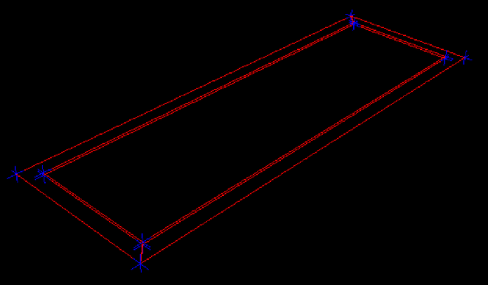
In the graphical area, the select surfaces (all of them in this example) should appear in red as in Figure 14.
Figure 14: The selected surfaces appear in red.
| 4. | To ensure that all surfaces will be selected, click All > OK. This returns the program to the Simple Fold panel. Click the Airbag plan button to define the airbag plane (see the A Few Notions of Geometry section for an introduction). See Figure 15. |
Figure 15: The plane selection panel.
|
| 5. | At the beginning of the folding process, there are no planes available yet. A new plane must be defined. Click the New plan button, enter a meaningful Title, and click the arrow icon ( ) to start selecting the nodes. After picking three nodes, the graphical area should be similar to what is seen in Figure 16. ) to start selecting the nodes. After picking three nodes, the graphical area should be similar to what is seen in Figure 16. |
Figure 16: The picked nodes appear as small red cubes.
| 6. | Click Check to check the plane. If it is OK, click Save and the new plane's name will appear in the list. Select it from the list; it is possible to hide it by clicking the "Eye-minus" icon ( ), and then click the Select button. The plane is selected. ), and then click the Select button. The plane is selected. |
| 7. | Proceed to the fold line definition by clicking the Fold line button. This will open the panel shown in Figure 17. |
Figure 17: The fold line selection panel.
|
| 8. | Click the New line button, enter the Title of the line, click the 2 x 3 coords label and enter the coordinates as shown in Figure 17 2. Click Check (be sure to note the line's orientation), then Save to create the line. |
| 9. | Select its name in the list, hide it from the display with the "Eye-minus" icon () (optional), and then click Select. The line is defined. |
Now it is possible to check if the fold definition is OK.
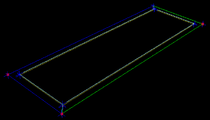
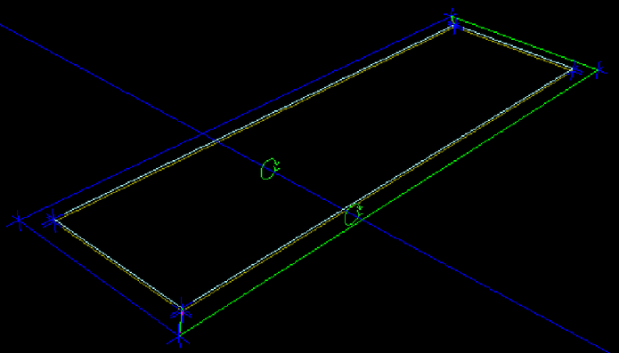
| 10. | Click the Check button and the fold and circular arrows showing the fold direction become visible (Figure 18). If this is unsuccessful, an error message in red appears in the message area. |
Figure 18: The circular arrows show the fold direction.
| 11. | If the fold definition is OK, click Do and the folded airbag appears in the graphical area (see Figure 19). |
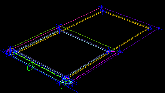
Figure 19: The airbag after a simple fold.
|
Reference
| 2 | The exact  coordinates values are not very important; the first one must be bigger than the second one in order for the line orientation to be correct. coordinates values are not very important; the first one must be bigger than the second one in order for the line orientation to be correct. |
See also
Initial Geometry Input
Call the Safety Tool
Create the Initial Geometry