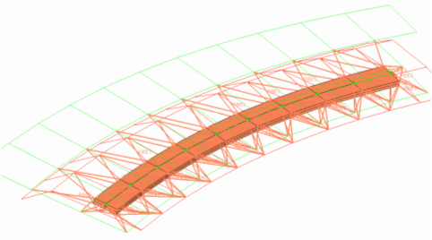
The feature enables you to create continuous HEXA welds from seam connectors. All of the required information is stored in the database and exported to the XML master connector file.
The welds can be realized from the Seam panel's seam and realize pages by specifying the required parameters.

The important points supported are:
| • | Allows all parameters to be defined at the time of realization. |
| - | Width: This is determined by the spacing of the seam connector. This can be defined during the creation of seam connector or edited later. |
| - | Depth: This defines the total width of the continuous HEXA weld in the direction perpendicular to the seam direction. |
| - | Strips: This defines the number of HEXA elements required along the depth. |
| - | Thickness: There are four options to define the thickness of the weld: shell gap, constant thickness, mid gap and average thickness. |
| - | Density: The number of HEXA elements required along the thickness. |
| • | Exporting and importing an XML MCF file of the seam connector will retain all the various realization parameters. |
| • | The continuous HEXA elements will be centered about the seam connector if the seam connector is not close to a free edge. If the distance between the seam connector and free edge of a component is less than half the width of the continuous HEXA, then the realization of HEXA elements will start from the seam connector and will be extruded in the direction away from the edge. |
| • | Ease of use through FE configuration definitions for each supported solver. |
| • | For Altair OptiStruct and Nastran solvers, the HEXA elements are tied to a shell using RBE3’s at locations where the HEXA nodes and shell nodes are non-coincident. If the HEXA nodes and shell nodes are coincident then RBE2's will be used to tie them. |
| • | For the LS-DYNA solver only, the shell gap thickness option is supported. If the HEXA nodes are co-incident with shell nodes then those shell nodes will be used to create HEXA elements. The HEXA elements at some or all nodes will be tied directly to the shells. |
The main requirements to successfully create the weld are:
| • | The connector’s links must be components or surfaces with mesh. |
| • | The shell elements must have valid thickness defined either through an attribute or a property. |
| • | The thickness, number of HEXA along the width and depth, and the depth values for the Continuous HEXA weld must be defined. |
| • | Solver-related information must be defined through a property script. |


