Engineering Solutions

Pedestrian Impact

Pedestrian Impact

Previous topic Next topic Expand/collapse all hidden text  

Pedestrian Impact

Previous topic Next topic JavaScript is required for expanding text JavaScript is required for the print function  

The Pedestrian Impact is a tool that generates an input deck for the simulating pedestrian head and leg impacts on vehicle hoods, windshields, bumper and bonnets. It conforms to the pedestrian safety regulations EuroNCAP, Homologation and ECER. The Pedestrian Impact tool automates the process with minimal input, therefore reducing model generation lead time.                                      

Pedestrian Impact provides the following features:      

The ability to automatically generate all wrap around distance (WAD) lines, side reference lines (SRL), SRL offset lines, bonnet leading edge (BLE) reference lines, bonnet rear reference lines (BRRL), bumper reference lines and BRRL offset lines for EuroNCAP, European Homologation and ECER pedestrian safety protocol.  
The ability to handle vehicle motion in the positive or negative X direction.
Generation of grid points for adult/child head impact.
Automatic position of the impactor with proper orientation at the target point without any penetration.
Option to specify depenetration offset distance and impact angles for head positioning.
The ability to review impactor positioning.
Generation of hard part distance contour to identify areas that may have been missed.  
The ability for global positioning of vehicle and automatic calculation of vehicle origin coordinates.
Automatic definitions of contacts, velocity and positioning of the impactor.
Supports LS-DYNA and Altair Radioss solvers.

Pedestrian Impact is available in the Crash LS-DYNA and Altair Radioss user profiles. It can be accessed by clicking Safety > Pedestrian Impact from the menu bar.      

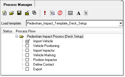
Invoking Pedestrian Impact opens a Process Manager tab that guides you through the process. You can go from one task to the next by clicking Next and Apply on the input panel.  

This tool imports the vehicle model and impactor. The impactor is positioned at the target location, per EuroNCAP protocol, Homologation and ECER regulations. The vehicle model should be in a plane parallel to xy-plane and the impactor should be at (0,0,0) with respect to the global coordinate system and aligned along the global positive x-axis.    

crash_pedestrian_impact_template

hmtoggle_plus1greyImport Vehicle

A panel, as shown below, appears to import the vehicle model.

crash_vehicle_import_panel

Perform the following steps:

1.Select the File type of the model.
2.Enter the file path for the Vehicle file or click the folder icon to browse for the file.
3.Click Import to import the model. A new include with the name Vehicle will be created and the model will be imported under that include.
4.In the Dir of vehicle motion field select the appropriate direction of vehicle motion.    
5.Select the Unit System.  
6.Select the Region to keep after trimming.
7.Enter the distance value from which the vehicle should be cut.
8.Clicking Preview shows the region that will be left after trimming.
9.Click Trim for trimming the vehicle model. This step is optional.
hmtoggle_plus1greyVehicle Positioning

A panel, as shown below, appears to position the vehicle in the vehicle coordinate system. This task is optional.

crash_vehicle_positioning_panel

Perform the following steps:

1.Specify the initial vehicle coordinates (before executing the translation or rotation task).
2.Select the entity (Ground or Vehicle) that needs to be rotated and/or translated.
3.To apply a rotation define the Rotation angle in degrees.      
4.Specify the Base Point coordinates or use the Base Node button to select the node from graphics.  
5.Click Rotate. Click Undo, if required.    
6.To apply a translation define the translation distance.  
7.Click Translate.  
8.The Show Ground checkbox allows you to toggle on or off the display of the Ground.
9.The Distance Measurement allows you to determine the distances from a selected Node to the ground and global origin along the ground normal direction. The calculated distances are displayed in the Distance to Ground and Distance to Global Origin fields.  
hmtoggle_plus1greyImport Impactor

Use this panel to import the impactor model.

crash_impactor_type_panel

For the Impactor Type select the appropriate option from the drop-down. Use the folder icon to browse and select the model files. Click Import to import the impactor model. A new include with the name Impactor will be created and the model will be imported in that include.          

The default location for different impactors are as follows:

Head: The axis of the head should be along +ve X-axis with its center of gravity at origin (0,0,0).
LowerLeg: The longitudinal axis of the impactor should be along the Z-axis with the center of its circular base at origin (0,0,0).
UpperLeg: The lateral axis of the impactor should be along +ve X-axis with the center of gravity at origin (0,0,0).

All of these locations are fixed irrespective of the vehicle's location.

hmtoggle_plus1greyVehicle Marking

Use this panel to mark side reference lines, wrap around distance (WAD) lines, grid points, per EuroNCAP, Homologation or ECER regulations, and create target point CSV for grid points.        

crash_vehicle_marking_panel

crash_car

The options in the panel perform the following actions:  

Regulation

Select EuroNCAP, Homologation or ECER.          

Dir of vehicle motion

Select -veX or +veX for the direction of vehicle motion.  

Regulation Version

EuroNCAP versions 6.1, 7.0 and 8.0 are supported, Homologation version UN GTR No. 9 is supported and ECER version UN GTR No. 9 is supported.    

Vehicle Front Components

Select the vehicle front components. Components within the bumper and the bonnet rear reference line (BRRL) on the outer surface of the vehicle are considered as vehicle front components. This may include the bumper, hood, fenders, headlights and front grill, depending on the model.                      

Wiper Components

Select the wiper components. This is optional. All of the components between the bonnet and the windshield (for example plenum and cowl components) should be selected as wiper components.            

Windshield and A-pillar Components

Select the windshield and A-pillar components. Required only for head impactors.      

Target Point CSV

Use the file icon to browse for and select the .csv file. Required only for head impactors.    

Side reference angle (deg)

The angle required to create the side reference line on selected components. The default value, per EuroNCAP, Homologation and ECER regulations, is set to 45 degrees. You can change the angle to between 35 and 55 degrees.

Front reference angle (deg)

The angle required to create the front reference line on selected components. The default value, per EuroNCAP, Homologation and ECER regulations, is set to 50 degrees. You can change the angle value to between 40 and 60 degrees.

Grid Step Distance (mm)

The distance between grid points. The default value, per EuroNCAP and Homologation regulations, is set to 100. The default value per ECER regulations is set to 165. You can change this for your requirements.      

Reference Resolution (mm)

The distance used while interpolating reference line points. This should always be less than or equal to half of the grid step distance. The lesser its value the more time it takes to create the reference lines, but the lesser value results in better overlapping of geometry and reference lines.    

Vehicle origin

Add entries with changed vehicle origin coordinates after executing the vehicle positioning task. The changed vehicle coordinates are calculated automatically based on coordinates provided in the initial vehicle origin in the Vehicle Positioning panel. For marking the correct reference lines, WAD lines and grid points these entries are disabled.      

BRRL (mm)

Specify the offset value for bonnet rear reference lines.

SRL (mm)

Specify the offset for side reference lines.

BRRL (mm)

The offset value required to create the BRRL offset line on selected components. You can change the offset value according to your requirements.    

SRL (mm)

The offset value required to create the SRL offset line on selected components. You can change the offset value according to your requirements.      

X (mm)

The X coordinate of vehicle origin is automatically calculated as per the vehicle movement in the positioning task.

Y (mm)

The Y coordinate of vehicle origin is automatically calculated as per the vehicle movement in the positioning task.

Z (mm)

The Z coordinate of vehicle origin is automatically calculated as per the vehicle movement in the positioning task.

Show Ground

Use the checkbox to show or hide ground.    

Create Target Nodes

Uncheck the checkbox if grid points should not be marked with head impactor.

Use Wiper for Wad Lines

Check the checkbox if wiper components selected should be taken into consideration for creating WAD lines.

Use Wiper for Reference Lines

Uncheck if wiper components selected should not be taken into consideration for creating reference lines.

Perform the following steps:      

1.Select the regulation type.  
2.Use the Vehicle Front Components toggle to select all of the front components of the vehicle (bumper, fender, head lamps, hood, and so on).
3. Use the Windshield and A-pillar Components toggle to select the windshield and A-pillar components.
4.Select Wiper Components, if required.    
5.Enter the file path or click the folder icon to browse for the .csv file for writing the target location information.
6.Default Reference values are given for side and front reference angles, offset values and for the grid step distance. Change the values, per your requirements.
7.Use Optional Wadlines to create your specified WAD lines. For multiple entries in the Wad Distances field separate with commas.
8.Click Create WAD to create WAD lines specified in the Wad Distances field.
9.Click Clear WAD to clear all previously created optional WAD lines.
10.Use the Show Ground checkbox to turn the display on or off for ground.
11.Use the Create Target Nodes checkbox to specify if adult and child target points should be created.
12.Use the Use Wiper for Reference Lines and Use Wiper for Wad lines, as per your requirement.
13.Click Apply to create the side, front reference line, WAD lines and grid points.  
hmtoggle_plus1greyPosition Impactor

A panel, as shown below, appears.

crash_position_head_panel

Perform the following steps:

1.Click the Components widget to select the Hood and Hard components. Click the Hide Comp button to hide components. This helps in selecting the under hood components.      
2.Click Draw to generate the Hard Part Distance Contour.  
3.Show/hide the Hard Part Distance Contour button to show or hide the panel.
4.Check/uncheck the Enable checkbox to show/hide the Hard Part Distance Contour.  
5.Click Import Target CSV, provide the existing .csv file path, and click Import.
6.Click Add New Target to select a new target location.
7.Click Update Target CSV if you want to update the .csv file.  
8.Select either Target Point Positioning or Contact Point Positioning for the head positioning. This option is available only for head impactor. Target point positioning positions the head impactor with its axis passing through the target point while the contact point positioning method positions the head so that its lowest point is on target location. For crash testing target point positioning should be used. Contact point positioning may help in understanding how sensitive impact location is, for example.        
9.Specify the offset required between the vehicle and the head model after positioning.    
10.To delete a row from the table, select the row to be deleted by clicking on the row and then click thetableDeleteSelected-24 icon.  
11.Click thetableDeleteAll-24 icon to delete the complete table.  
12.To export the CAD of the target points, specify the target sphere size in the Target Sphere Radius field.
13.Enter the file path or click the folder icon to browse and specify the output CAD file information in the Output Target file field.
14.Click Export Target to export the target points and reference lines as an .iges file.  
15.The Review Exported Target checkbox allows you to review the exported points in the current graphics window.
16.Click Apply to go to the next task.
hmtoggle_plus1greyDefine Contact

This panel is used to define contact between the impactor and the vehicle components. The following contact will be created:

LS-DYNA user profile: *CONTACT_AUTOMATIC_SURFACE_TO_SURFACE
Altair Radioss user profile: two symmetric interface type 7

crash_define_contact_panel

Altair Radioss user profile

crash_define_contact_panel_lsdyna

LS-DYNA user profile

Perform the following steps:  

1.Select either Create New Contact or Use Existing Contact File for the contact method.
2.If the contact method is Create New Contact click the Vehicle Component toggle and select the vehicle components. If vehicle components are already selected in the Vehicle Marking task, use the checkbox to use them for contact creation.
3.If the contact method is Use Existing Contact File enter the contact file path or click the folder icon to browse for the file.
4.Click Apply to create contact.
hmtoggle_plus1greyExport

A list of all of the target points is displayed in a table. The location as well as the velocity is displayed in this table for each target point. The velocity field is editable.

LS-DYNA user profile

A panel, as shown below, appears to export decks for the selected target points for the LS-DYNA solver.

crash_export_panel

Altair Radioss user profile

A panel, as shown below, appears to export decks for the selected target points for the Altair Radioss solver.

crash_export_panel_radioss

To export the model for different target points perform the following steps:

1.Select the points that need to be exported by clicking the checkboxes in the Export options column. The select all adult points and select all child points buttons easily allow you to select only child/adult points.  
2.Define the path in which the files should be exported in the Output Directory field. If the directory does not exist, it will be created along with the sub folders that will contain the files for each target point.  
3.For the LS-DYNA user profile select the Control Card File. For the Altair Radioss user profile define the engine file parameter (duration, time step, and so on). The engine file can be edited by clicking the Engine File Preview button.
4.Select which file should be exported in the Export options.
5.Click Export to export the input deck for the selected target locations.
6.For the Altair Radioss user profile only the Radioss button allows you to submit the job to the local Altair Radioss installation.

Export directory structure

This tool exports the decks in a folder structure with different includes for the master model. A typical export directory of the tool is shown in the image below.        

export_directory_structure

For multiple locations multiple directories are created. The directories are named with respect to the target location name.

Vehicle, Contact, Impactor, ControlCard and HM_Pedestrian directories are common for all target locations.        

The Vehicle and Impactor directories contain vehicle and impactor files selected for creating decks.
The Contact directory contains the contact include file with contact definitions.
The HM_Pedestrian directory contains hard part distance contour plots and WAD line collector includes. This folder is created for post-processing.
The ControlCard file directory contains the control card file for the Dyna solver (only for the LS-DYNA template).

The folder named C_0_0 (based on target location names) contains:

Altair Radioss user profile

The master file for that location.
The engine file.
An include file containing the transformation and velocity card (allows you to move the impactor to the target point location).

LS-DYNA user profile

The master file for that location. This file also contains the initial velocity and the transformation card.


See Also:

CRASH-2200: Pedestrian Head Impact Simulation

Safety Menu

Crash Application