The scaling menu helps you to stretch the parts.
Example:
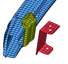
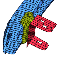
To change the mesh of the red part to join it to the yellow part, use the Scaling menu.
|
|
By defining a direction and a scale factor, the mesh can be modified:
|
|
| 1. | Select the Scaling window ( ) sub-window. ) sub-window. |
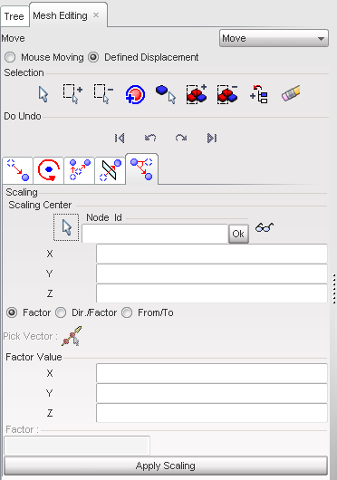
| 2. | Define the Scaling Center by using the following: |
| • | Click  and in the graphic window, pick one node. and in the graphic window, pick one node. |
| • | Fill in the X, Y, and Z fields. |
| • | Enter a node ID in the Node Id field. |
From this point, three different options are available to define the scaling direction and the scaling factor.
Enter a factor in the three directions:
| 1. | Click the Factor radio button to activate it. |
| 2. | Fill in the X, Y, and Z fields with the Factor Value in each direction. |
| 3. | Click Apply Scaling as many times as necessary to apply the defined displacement. |
| 4. | If necessary, click the functions to undo or redo the displacement. |
| 5. | Click Close to close the menu. |
Enter a direction and a factor:
| 1. | Click the Dir./Factor radio button to activate it. |
| 2. | Define a direction by using one of the following: |
| • | Click  and in the graphic window, pick two nodes. and in the graphic window, pick two nodes. |
| • | Fill in the X, Y, and Z fields for the Vector Coordinates |
| 3. | Enter the scaling factor in the Factor field. |
| 4. | Click Apply Scaling as many times as necessary to apply the defined displacement. |
| 5. | If necessary, click the functions to undo or redo the displacement. |
| 6. | Click Close to close the menu. |
Pick a vector (the vector will define a direction and a factor):
| 1. | Click the From/To radio button to activate it. |
| 2. | Click and, in the graphic window, pick two nodes. |
| 3. | Click Apply Scaling as many times as necessary to apply the defined displacement. |
| 4. | If necessary, click on the functions to undo or redo the displacement. |
| 5. | Click Close to close the menu. |
Go to
Move


