|
»Click here to display Table of Contents«
|

Laminate Tool |

|

|

|

|
|
Laminate Tool |
|
|
|

|
|
»Click here to display Table of Contents«
|
Laminate Tool |
|
|
|
|
|
Laminate Tool |
|
|
|
|
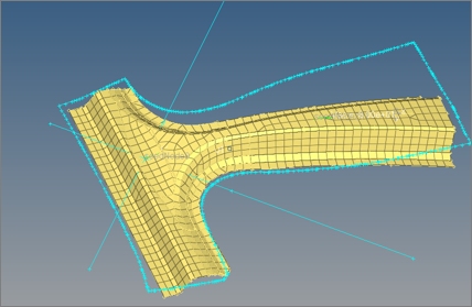
Fiber angle changes with respect to a material system when a flat composite sheet is laid on surfaces of a part which is highly curved in bi-directions. This also changes the ply thickness. It is no longer the nominal ply angle ( 0,45,-45, 90). If the change in angle or thickness is significant, it will lead to a change in the stiffness of a part.
Use the Laminate Tool to calculate fiber angles and thickness changes with respect to an element material system. This tool creates a distribution table of drape angle changes, change the thickness of each ply, and flatten the shape of a ply that needs to be fabricated before laying on the mold. Invoke the Laminate Tool, in the Model browser, by right-clicking on the Plies folder or individual plies and selecting Drape > Laminate Tools from the context menu.
The Laminate tool is available in the Altair OptiStruct and Abaqus user profiles.
| 1. | Create a ply shape (elements) by realizing the plies. Each ply must have elements associated with it. If it has been draped already, delete the Table entity associated with that ply. |
| 2. | In the Model browser, right-click on the ply/plies to be draped and select Drape > Laminate Tools from the context menu. The Laminate Tools Drape dialog opens. |
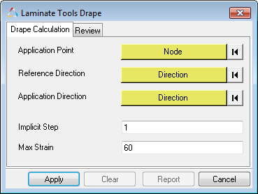
| 3. | In the Drape Calculation tab, define draping simulation settings. |
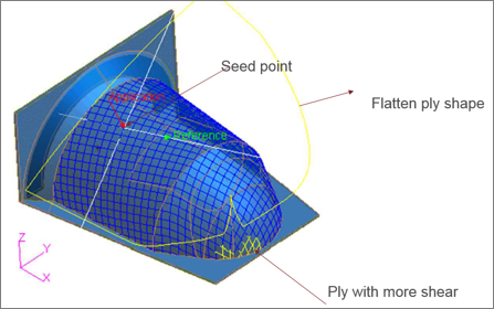
| a. | Using the Application Point selector, select a node to indicate where the ply is first placed on the surface. |
| b. | Using the Reference Direction selector, select two nodes to indicate the reference direction (zero degree ply direction). |
The starting/initial ply angle is automatically determined based on this reference direction.
| c. | Using the Application Direction selector, select a vector to indicate how a ply is placed. If this direction (vector) is not selected, the element normal will be used as the application direction. |
| d. | In the Implicit Step field, enter a draping step length. |
The average element size at that point could be a good step size.
| e. | In the Max strain field, enter a value to color the drape lines. If the % shear is above this value, yellow and red contours will start appearing on the drape line, which indicates you may need to cut the fiber in order to relieve strain/wrinkling |
| f. | Click Apply. |
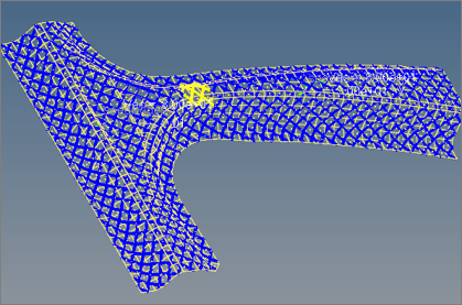
| 4. | In the Review tab, select a review option to read the results. |
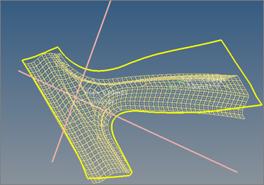
| • | Drape Lines. Initially an unidirectional ply start with a 90 degree angle between the weft and wrap lines. As the ply is draped over a curved surface, this angle changes. If the shear is more than max strain, than the color changes from blue to yellow to red. |
| • | Flat Lines. Review the flat ply shape that is needed to cover the surface. |
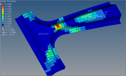
| • | Drape Thickness. Contour the distribution of thickness changes. |
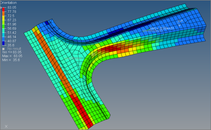
| • | Drape Orientation (shear). Contour the shear (angle changes from 90 degrees). |
| 5. | In the Export tab, export the flatten ply shape as geometry (STEP format). |
The Flat ply shape can be exported one ply at a time as STEP geometry.