In this tutorial you will learn how to
| • | Generate a structured quad surface mesh |
| • | Adjust the boundary layer thickness manually |
| • | Generate a hybrid grid (tetramesh with boundary layer) |
| • | Export the model for a CFD solver of your choice |
The model file used in this exercise can be found in the es.zip file. Copy the file(s) from this directory to your working directory.
| 1. | From the menu bar, select Preferences > User Profiles or click  on the Standard toolbar. on the Standard toolbar. |
| 2. | Select Engineering Solutions > CFD. |
|
| 1. | Click the Open Model icon  on the Standard toolbar. on the Standard toolbar. |
| 2. | Select the wing.hm file. |
| 3. | Click Open to load the file. |
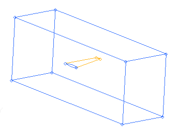
| 4. | In the Model browser, click Component and expand the folder, then right-click box and select Hide. |
| 5. | Right-click plane and select Show. |
|
| 1. | Click Mesh > Surface Mesh 2D > Automesh. |
| 2. | Click the size and bias subpanel. |
| 3. | Set the element size = field to 5.0. |
| 4. | Set the mesh type to quads only. |
| 5. | Ensure that both the size and skew checkboxes are activated. |
| 6. | Ensure toggles are set to elems to surf comp and first order. |
| 7. | Click surfs. In the graphics area, use the Shift key and the left mouse button to draw a box around the wing to select the entire image. |
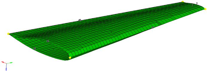
| 8. | Click mesh. A message on the status bar indicates the number of elements created. |
|
| 1. | While in the density subpanel, change the elem density = field to 17. |
| 2. | Click edge just above the elem density field and graphically select both left-hand edges of the wing. The entire edge is selected. |
| 3. | Rotate the model and repeat Step 2 for the other end. |
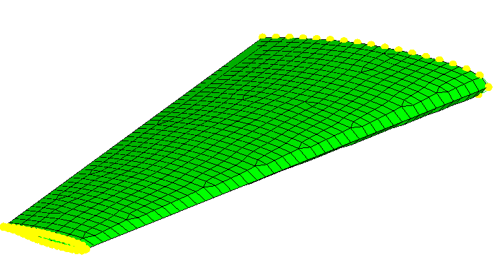
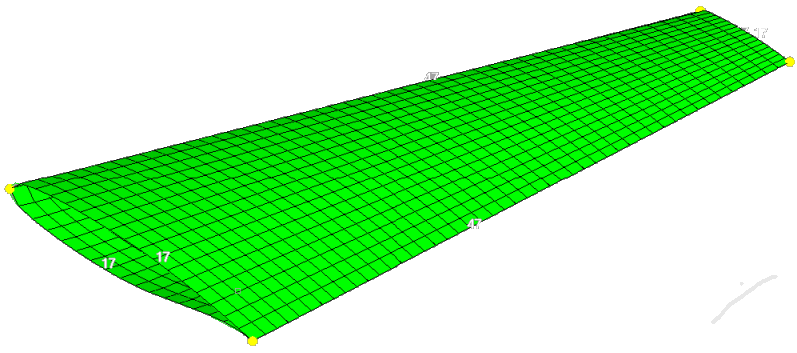
To get a structured quad mesh adjust the number of nodes on the edges in such a way so that two opposite edges have the same number of nodes. See the image below:
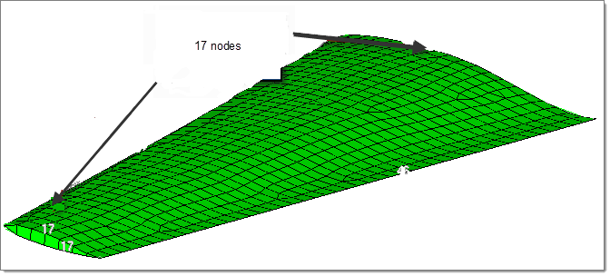
| 4. | Click edge next to adjust and select the edge as shown in the image below: |
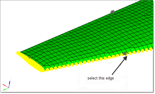
| 5. | Now adjust the node seeding on the two remaining edges (leading edge and training edge) to 47 to get a uniform quad mesh. |
| 7. | Click return to close the panel. |
|
| 1. | Click BCs > Components > Single. |
| 2. | Enter the name of the new component as BL_thin and click Create and then Close. |
| 4. | With elems highlighted, use the SHIFT key and the left mouse button to draw a box around a portion of the elements on the wing (see the image below). |
| 5. | Click dest component and select the component BL_thin. |
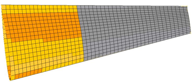
| 6. | Click move, and then click return. |
|
| 1. | In the Model browser, turn on the display of the box component, and then click F on the keyboard to fit the model into the graphics region. |
| 2. | Click Mesh > Surface Mesh 2D > Automesh and then select the size and bias subpanel. |
| 3. | With surfs highlighted, select the six surfaces of the box. |
| 4. | Set the element size field to 30, and change the mesh type toggle to trias. |
| 6. | Double-click return to close the panels. |
|
| 1. | Click Mesh > Volume Mesh 3D > CFD tetramesh. |
| 2. | Click the Boundary selection subpanel. Under the heading With BL (fixed), click comps and select the plane and BL_thin components. |
| 3. | Under the heading W/o BL (float), click comps and select the box components. |
| 4. | Click the BL parameters subpanel. |
| 5. | In the Number of Layers field, enter 4. |
| 6. | In the First layer thickness field, enter 0.3 |
| 7. | Check the boxes for BL reduction and Pre calc and then click Manual to open the Distributed BL Thickness Ratio dialog. |
| Note: | In the dialog, you can select nodes or components, and define a scaling factor for the boundary layer thickness at this location. For example, a scaling factor of 0.5 will reduce the BL thickness in this region to one half of the original BL thickness. |
|
| 8. | In the dialog, click Components. |
| 9. | Click Select Components and select the component BL_thin. |
| 11. | In the Thickness Ratio field, enter 0.1. |
| 12. | Click Assign, and then click Close. The defined scaling factor is now stored in the load collector ^CFD_BL_Thickness, as shown in the Model browser. |
| Note: | For all of the nodes in the selected component BL_thin, the boundary layer thickness will be reduced to 1/10 of its initial size. A smooth thickness transition will be used. |
|
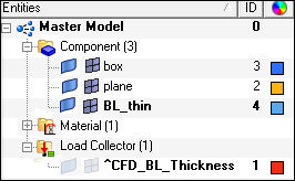
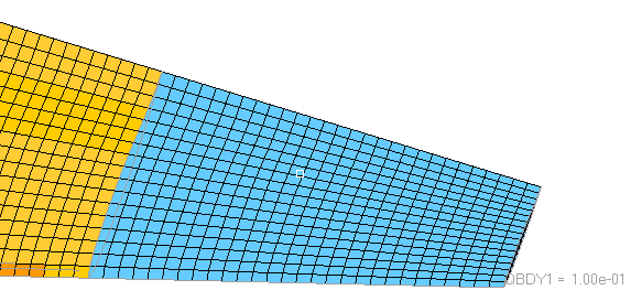
| 13. | In the Model browser, right-click the box component and select Hide. Right-click the load collector ^CFD_BL_Thickness and select Show. Check the value of the scaling factor to make sure it is correct and if it is attached to the correct component. |
| 14. | Click the Tetramesh parameters subpanel. Select Interpolate for the tetrameshing growth algorithm behavior. |
| 15. | Click mesh. Two new components are generated containing the boundary layer elements and tetra elements. |
| 16. | To check the result, mask parts of the mesh and compare the thickness of the boundary layer for the plane component with the thickness of the BL_thin component. You can do this in the Distance panel. You will see that the thickness ratio is 1/10, as expected. |
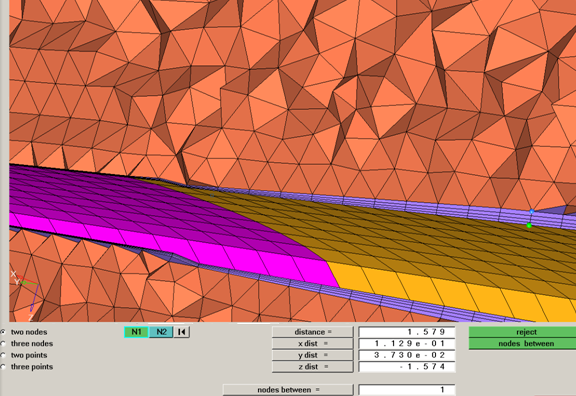
Due to smoothing algorithms for the boundary layer, the thickness ratios can differ from the user-defined values, for some use cases.
|
| 1. | In the Model browser, right-click Components and click Show to display all components. |
| 2. | Click BCs > Components > Single. Enter the new name as fluid. |
| 3. | Repeat Step 2 to create more collectors, with the names inflow, outflow, wall_wing and wall_slip. |
| 4. | Click the Mask tab, click the 1 in the row 3D elements to display only volume elements. |
| 6. | Click elems and select displayed. |
| 7. | Click dest component and select the component fluid. |
| 8. | Click move, and then click return. |
| 9. | In the Mask tab, click the 1 in the row 2D elements to display only shell elements. |
| 10. | Click Mesh > Delete > Elements. |
| 11. | Click elems and select displayed. |
| 12. | Click delete entity and then click return. |
| 13. | In the Model browser, right-click fluids and select Make Current, and then right-click it again and select Show. |
| 15. | Click comps and select the fluid component. Click find faces and then click return to close the panel. |
| 16. | A new component named ^faces is created and displayed in the Model browser. Right-click it and select Isolate. |
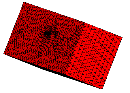
| 18. | Select the elements lying on the inflow boundary, and move them to the inflow component. The easiest way to do this is to select a single element on the inflow boundary and then select by face from the extended entity selector. Repeat this step selecting the elements on the outflow boundary, and moving them to the outflow component. |
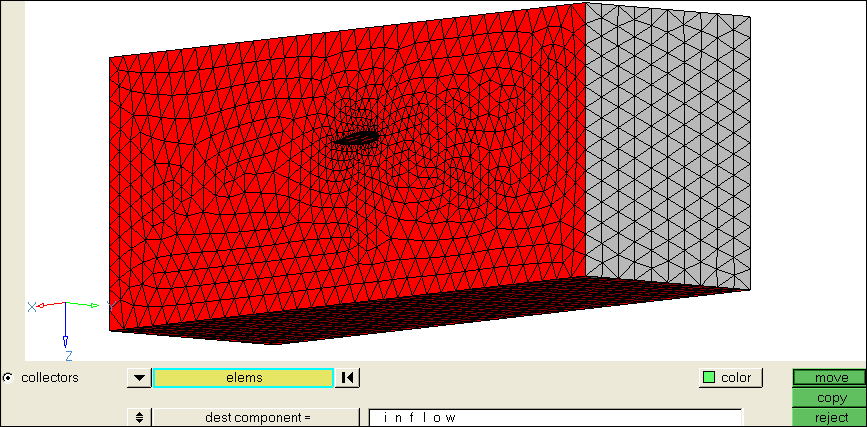
Inflow boundary selected for the inflow component
| 19. | Move the shell elements from the four other sides to the component wall_slip. |
| 20. | Move the shells on the wing profile to the wall_wing component. Click return to close the panel. |
| 21. | The collector ^faces should now be empty and can be deleted by right-clicking it in the Model browser. |
| 22. | Delete the other empty components - plane, box, BL_thin, CFD_bl001 and CFD_tetcore001. |
|
| 1. | Right-click Components in the Model browser and select Show. |
| 2. | Click the Export Solver Deck icon  and export the model for the CFD solver of your choice. and export the model for the CFD solver of your choice. |
|


